Method for effectively reducing electromagnetic emission in local interconnection network (LIN) driver

A driver circuit, driver technology, applied in the direction of electrical components, logic circuits, single pulse train generators, etc.

Active Publication Date: 2013-07-03
STMICROELECTRONICS SHANGHAI R&D
View PDF4 Cites 6 Cited by
  • Summary
  • Abstract
  • Description
  • Claims
  • Application Information

AI Technical Summary

Problems solved by technology

However, the steep edges of the step current cause significant levels of radiated emissions on the LIN bus

Method used


Image

  • Method for effectively reducing electromagnetic emission in local interconnection network (LIN) driver
  • Method for effectively reducing electromagnetic emission in local interconnection network (LIN) driver
  • Method for effectively reducing electromagnetic emission in local interconnection network (LIN) driver

Examples


Embodiment Construction

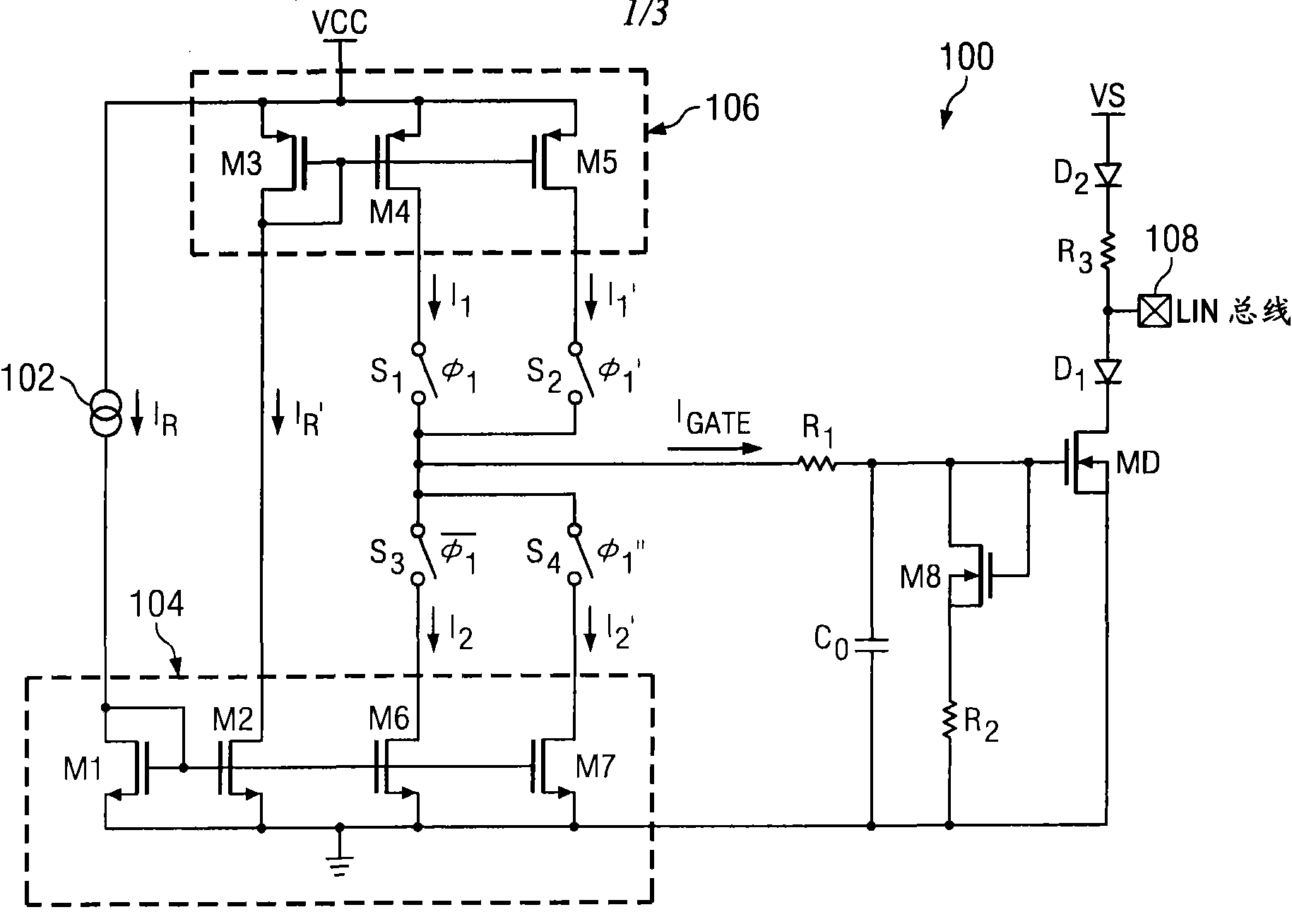
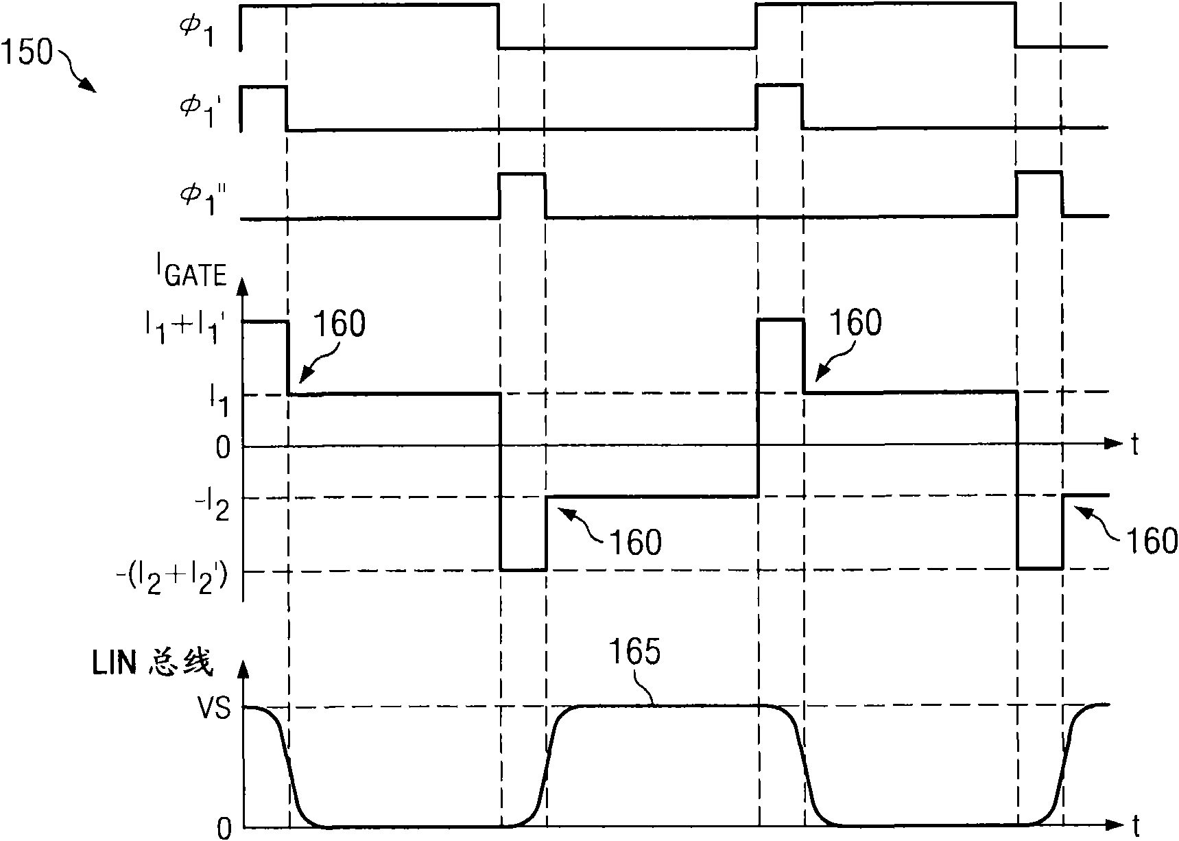
[0012] refer to Figure 1A and Figure 1B , where an embodiment of a conventional LIN driver circuit 100 is shown in Figure 1A , and here with Figure 1B Its corresponding timing diagram and waveform 150 illustrated in , are discussed in conjunction. A conventional LIN driver circuit 100 includes supplying a reference current I to a first current mirror 104 R Referring to the current source 102, the first current mirror 104 includes a transistor M1 and a transistor M2. Transistor M1 can be sized according to transistor M2 to set the mirror reference current I R ', the current is supplied to the second current mirror 106 comprising transistors M3, M4 and M5. Transistor M4 can be sized relative to transistor M3 to set a constant charge current I 1 , the transistor M4 passes the first clock signal Φ according to 1 The phase of the switch S is operated 1 is operatively connected to the gate of transistor MD operating as a low-side driver. Transistor M5 can be sized relativ...


PUM


Abstract

The invention relates to a method for effectively reducing electromagnetic emission in a local interconnection network (LIN) driver, and provides an LIN driver circuit which adopts a charging or discharging current applied to a gate of a driver transistor coupled to an LIN bus. The charging current comprises a constant charging current and an additional soft charging current; and the discharging current comprises a constant discharging current and an additional soft discharging current. By a soft charging or discharging component, the electromagnetic emission on the LIN bus is obviously reduced.

Description

technical field [0001] The present invention relates generally to local interconnect network (LIN) circuits, and more particularly to reducing electromagnetic emissions in integrated LIN drivers. Background technique [0002] Industry specifications for LIN drivers typically specify that the transmitted signal be shaped to have a predetermined slope in order to reduce electromagnetic emissions at high frequencies. Unfortunately, the small slope required often results in an invalid duty cycle, which thus leads to errors in the data transmission. In trying to solve this problem, many conventional LIN drivers use a step current as the gate charge / discharge current. However, the steep edges of the step current cause significant levels of radiated emissions on the LIN bus. Accordingly, there is a need for a LIN driver operable to ensure signal integrity while achieving reduced electromagnetic emissions on the LIN bus. Contents of the invention [0003] The present disclosure...

Claims


Application Information

Patent Timeline
IPC IPC(8): H04L25/02H03K19/094
CPCH03K4/023H04L25/08H03K3/78
Inventor 沈慧尹小平
Owner STMICROELECTRONICS SHANGHAI R&D
Why Eureka
Try Eureka