
Hydraulic jet packer applicable to multilevel hydraulic jet fracturing

A technology of hydraulic jetting and tools, applied in the directions of sealing/packing, production fluid, wellbore/well components, etc., can solve problems such as packer failure

Inactive Publication Date: 2013-07-03
BC P INC CHINA NAT PETROLEUM CORP
View PDF7 Cites 19 Cited by
  • Summary
  • Abstract
  • Description
  • Claims
  • Application Information

AI Technical Summary

Problems solved by technology

With the increase of hydraulic jet fracturing layers and well depth in oil wells and horizontal wells, the packers suitable for the hydraulic jet string structure will be in high temperature and high pressure environment for a long time, and need to be repeatedly set. The working conditions can easily lead to the failure of the packer

Method used


Image

  • Hydraulic jet packer applicable to multilevel hydraulic jet fracturing
  • Hydraulic jet packer applicable to multilevel hydraulic jet fracturing
  • Hydraulic jet packer applicable to multilevel hydraulic jet fracturing

Examples


Embodiment 1

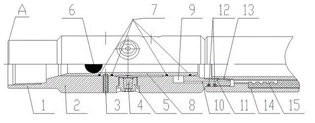
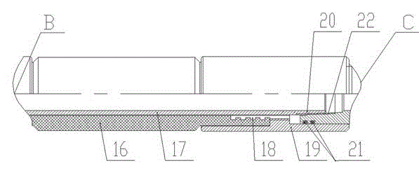
[0032] As a preferred embodiment of the present invention, the present invention includes a spray gun, a packer and a sliding sleeve seating joint, one end of the packer is connected to the spray gun, the other end of the packer is connected to the sliding sleeve seating joint, and a sliding sleeve is arranged in the spray gun , the inner diameter of the sliding sleeve is variable, from the spray gun to the direction of the joint where the sliding sleeve is located, the inner wall of the sliding sleeve is composed of three sections with successively smaller inner diameters, and a ball seat is arranged inside the sliding sleeve. In specific applications, the specifications of the three inner diameters that become smaller in turn are: 28mm, 32mm and 35mm.

Embodiment 2

[0034] As another preferred embodiment of the present invention, the outer wall of the spray gun is provided with scissors, and the outer wall of the sliding sleeve is provided with a scissor slot matching with the scissors, and the sliding sleeve is fixed to the spray gun via the scissors. All the other are with embodiment 1.

Embodiment 3

[0036] As another preferred embodiment of the present invention, the spray gun includes a spray gun body and a nozzle arranged on the spray gun body, the sliding sleeve is arranged in the inner cavity of the spray gun, and the sliding sleeve and the inner cavity of the spray gun are connected by a transition fit; the sliding sleeve The sleeve seating joint includes the upper end of the sliding sleeve seating joint, the lower end of the sliding sleeve seating joint and the baffle of the sliding sleeve seating joint; the packer includes a rubber sleeve and a center pipe arranged in the rubber sleeve, and the upper end of the rubber sleeve is connected to the upper rubber sleeve seat. The lower end of the rubber cartridge is connected to the lower rubber cartridge seat, the upper end of the spray gun body is connected to the oil pipe, the lower end of the spray gun body is respectively connected to the upper end of the central pipe and the upper rubber cartridge seat, the lower rub...


PUM


Abstract

The invention discloses a hydraulic jet packer applicable to multilevel hydraulic jet fracturing, and relates to the technical field of design and manufacture of acid fracturing technical equipment. The hydraulic jet packer comprises a spray gun, a packer and a sliding sleeve standing joint, wherein one end of the packer is connected with the spray gun, and the other end thereof is connected with the sliding sleeve standing joint; a sliding sleeve is arranged in the spray gun, and the inner diameter of the sliding sleeve is variable; and in the direction from the spray gun to the sliding sleeve standing joint, the inner wall of the sliding sleeve is composed of three structures with smaller inner diameters in proper sequence; and a ball seat is arranged in the sliding sleeve. With adoption of the hydraulic jet packer, selectable seat sealing can be realized; multilevel hydraulic jet fracturing construction can be completed; and integration of abrasive blasting perforation and mechanical sealing and separation is also realized.

Description

[0001] technical field [0002] The invention relates to a hydraulic jet packing tool suitable for multi-stage hydraulic jet fracturing, which is used for well completion stimulation measures in the oil and gas drilling process, and relates to the technical field of design and manufacture of acidizing fracturing technical equipment. Background technique [0003] Hydrojet segmental modification is the product of the combination of hydrojet and fracturing technology, involving perforation and fracturing stimulation measures; one string can be used to realize multi-stage construction in horizontal wells, and it can be used in open holes, cement-consolidated casings, and unconsolidated casings. Fracturing is carried out under various completion methods such as knotted screen pipes, and the construction efficiency can be greatly improved. [0004] Among the prior art, the following patent applications are related to packer technology: [0005] The publication number is CN1026502...

Claims


Application Information

Patent Timeline
Patent Type & Authority Applications(China)
IPC IPC(8): E21B43/114E21B33/126E21B43/26
CPCE21B33/128E21B43/25E21B43/26
Inventor 邓小强孙虎周丰王祖文苏敏文曹欣张冕韩虎成王建树韩文哲张文李景斌张波徐迎新高红平
Owner BC P INC CHINA NAT PETROLEUM CORP
Learn More