Radio frequency signal source

A kind of radio frequency signal source, signal technology

Active Publication Date: 2013-06-26
RIGOL
View PDF4 Cites 11 Cited by
  • Summary
  • Abstract
  • Description
  • Claims
  • Application Information

AI Technical Summary

Problems solved by technology

[0005] In addition, the introduction of a frequency division module or a frequency multiplier module will inevitably introduce insertion loss, and the introduction of an attenuation module will also introduce insertion loss
And this part of the loss introduced will usually gradually increase with the increase of frequency
In the prior art, an amplifier is generally used to make up for this part of the loss. However, the gain of the amplifier also decreases with the increase of the frequency, which will cause the higher the frequency, the greater the loss and the greater the amplification gain in the entire frequency range. Small, unable to achieve consistency of signal amplitude across the frequency band

Method used


Image

  • Radio frequency signal source
  • Radio frequency signal source
  • Radio frequency signal source

Examples


Embodiment 1

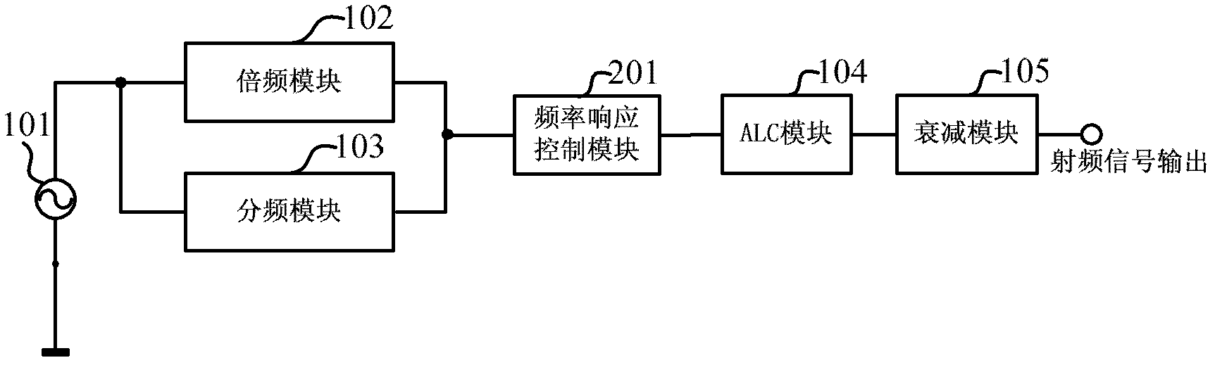
[0025] Such as figure 2 As shown, this embodiment provides a radio frequency signal source, the radio frequency signal source includes: a signal oscillator 101, a frequency multiplication module 102, a frequency division module 103, an ALC module 104 and an attenuation module 105, and the radio frequency signal source also includes: Frequency response control module 201 . The frequency response control module 201 is after the frequency multiplication module 102 and the frequency division module 103, and before the ALC module 104, that is, the signal input terminal of the frequency response control module 201 is connected to the output terminal of the frequency multiplication module 102 and the frequency division module 103, and the frequency response control module The signal output end of 201 is connected to the input end of the ALC module 104 . The main function of the frequency response control module 201 is to adjust the difference in amplitude of different frequency sig...

Embodiment 2

[0031] In the above embodiments, the variable attenuator 401 is used for adjustment. In actual use, the variable attenuator 401 can also be replaced with a variable gain amplifier for design, and the frequency response can be compensated by adjusting the gain of the variable gain amplifier. . Such as Image 6 as shown, figure 2 The frequency response control module 201 includes: a variable gain module 601 and an amplifier 302 .

[0032] The variable gain module 601 receives an input signal and is used for adjusting the gain value of the signal according to the frequency change of the signal. The signal input terminal of the amplifier 302 is connected to the output terminal of the variable gain module 601 for compensating the insertion loss of the variable gain module 601 .

[0033] Such as Figure 7 As shown, the variable gain module 601 includes: a variable gain amplifier 701 , a digital-to-analog converter 402 and an FPGA 403 .

[0034] The FPGA403 generates a control ...


PUM


Abstract

The invention provides a radio frequency signal source which comprises a signal oscillator, a frequency multiplication module, a frequency demultiplication module, an Adaptive Logic Circuit (ALC) module, an attenuation module and a frequency response control module, wherein the signal input end of the frequency response control module is connected with the output end of the frequency multiplication module and the output end of the frequency demultiplication module, and the signal output end of the frequency response control module is connected with the input end of the ALC module. The frequency response control module comprises a changeable attenuation module and an amplifier, wherein the changeable attenuation module receives input signals and is used for adjusting the amplitude of the input signals to be in a preset range; and the signal input end of the amplifier is connected with the output end of the changeable attenuation module, and the amplifier is used for compensating inserting loss of the changeable attenuation module. The radio frequency signal source can adjust frequency response caused by radio frequency link by being additionally provided with the frequency response control module, greatly reduces requirements for ALC dynamic range, reduces design difficulty and saves design and debugging time.

Description

technical field [0001] The invention relates to radio frequency signal technology processing technology, in particular to a radio frequency signal source. Background technique [0002] In order to ensure the accuracy of the output amplitude of the RF signal source, an automatic gain control loop (Automatic Gain Control, AGC, also known as an automatic level control loop (Auto Level Control, ALC)) is generally designed to ensure, such as figure 1 As shown, the ALC module 104 is added before the attenuation module 105 . figure 1 The radio frequency signal source includes: a signal oscillator 101 , a frequency multiplication module 102 , a frequency division module 103 , an ALC module 104 and an attenuation module 105 . The signal oscillator generates a signal with a frequency range of f1-f2 (generally an octave range) through oscillation, and because the frequency f3-f4 of the final signal output is far beyond this frequency range, that is, f3<f1, f4>f2 , so the freque...

Claims


Application Information

Patent Timeline
IPC IPC(8): H03G3/30H04B1/02
Inventor 沈艳梅何毅军王悦王铁军李维森
Owner RIGOL
Why Eureka
Try Eureka