Fan blade

A fan blade and fan technology, which is applied to wind turbines, wind turbine components, engines, etc., can solve problems such as damage to fan blades, buckling failure of fan blades, and large loads, so as to improve buckling resistance, avoid glue opening, and improve Effects on Structural Properties

Inactive Publication Date: 2013-06-26
SINOVEL WIND GRP
View PDF6 Cites 7 Cited by
  • Summary
  • Abstract
  • Description
  • Claims
  • Application Information

AI Technical Summary

Problems solved by technology

[0004] The fan blade structure in the prior art can be applied to wind turbines with a power generation capacity of the kilowatt level. However, with the improvement of the power generation capacity of the wind turbines, the power generation capacity of many wind turbines has reached the megawatt level, and the length of the blades is greatly increased. increase, and the load received is also greater; therefore, when this fan blade structure in the prior art is used in a megawatt-level wind turbine, due to the insufficient stability of the fan blade trailing edge, the trailing edge of the fan blade often appears buckling failure; in addition, the adhesive joint between the inner skin of the upper shell and the inner skin of the lower shell at the trailing edge often occurs, which causes damage to the fan blades and affects the normal power generation of the wind turbine

Method used


Image

  • Fan blade
  • Fan blade

Examples


Embodiment Construction

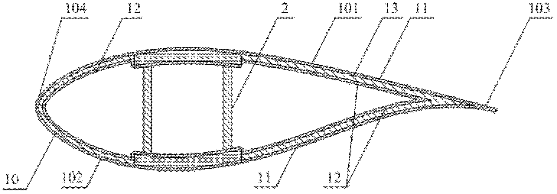
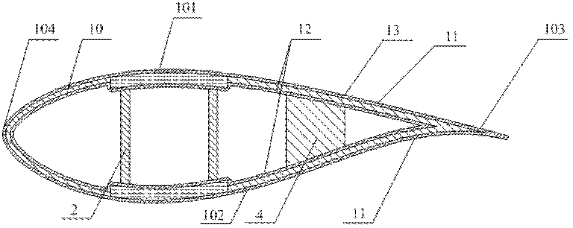
[0014] figure 2 It is a schematic cross-sectional structure diagram of an embodiment of the fan blade of the present invention. Please refer to figure 2 , the present embodiment provides a fan blade, including: a closed fan casing 10 formed by butting the upper casing 101 and the lower casing 102, and a shear web 2 is arranged in the cavity formed inside the fan casing 10 , the top and bottom ends of the shear web 2 are fixedly connected to the beam caps on the upper shell 101 and the lower shell 102 respectively, and a The connecting body 4 is fixedly connected to the upper shell 101 and the lower shell 102 respectively.

[0015] Specifically, the upper shell 101 and the lower shell 102 are docked to form a closed fan casing 10, and the tip formed by the docking of the upper shell 101 and the lower shell 102 is the rear edge 103 of the fan blade, and the rear edge 103 is relatively smooth. One end is the front edge 104; the beam caps can be respectively fixedly embedded ...


PUM


Abstract

The invention provides a fan blade which comprises a sealed fan shell body. The fan shell body is formed by an upper shell and a lower shell in a butt joint mode. A shearing resistance web is arranged inside a cavity formed by the fan shell body. The top end and the bottom end of the shearing resistance web are respectively and fixedly connected with a beam cap on the upper shell and a beam cap on the lower shell. A connecting body is arranged between the shearing resistance web and the rear edge of the fan blade inside the cavity, and the connecting body is respectively and fixedly connected with the upper shell and the lower shell. The fan blade improves the bulking resistance capacity of the rear edge of the fan blade, the tackless phenomenon at the position of the rear edge of the fan blade is effectively avoided through fixed connection between the upper shell and the connecting body and the fixed connection between the lower shell and the connecting body, failures caused by insufficient stability of the rear edge of the fan blade are prevented, and therefore normal power generation of a wind turbine generator is guaranteed.

Description

technical field [0001] The invention relates to the manufacturing technology of wind power generating set equipment, in particular to a fan blade. Background technique [0002] Wind power generation is an effective way to achieve energy saving and emission reduction. Fan blades are one of the core components of fan unit equipment. At the same time, the main load of the fan is generated by the blades rotating against the wind. Therefore, the structure of the fan blade directly determines the overall performance of the fan. [0003] figure 1 It is a schematic cross-sectional structure diagram of a fan blade in the prior art. like figure 1 As shown, the fan blade in the prior art includes a closed fan casing 10 formed by butting the upper casing 101 and the lower casing 102, and the outer surfaces of the upper casing 101 and the lower casing 102 constituting the fan casing 10 are respectively The negative pressure surface and the pressure surface, the tip where the negati...

Claims


Application Information

Patent Timeline
Patent Type & Authority Applications(China)
IPC IPC(8): F03D11/00
Inventor 唐超贾海涛金宝年刘作辉张芹
Owner SINOVEL WIND GRP
Why Eureka
Try Eureka