
Machining method of friction welding of forged steel piston

A processing method and friction welding technology, which is applied to pistons, engine components, machines/engines, etc., can solve the problems of increasing the risk of piston burning and cracking, reducing the fluidity of cooling oil, occupying the space of cooling oil passages, etc., and achieving production efficiency High, the effect of reducing the weight of the piston and reducing the load

Inactive Publication Date: 2013-06-26
DONGFENG PISTON & BEARING
View PDF7 Cites 6 Cited by
  • Summary
  • Abstract
  • Description
  • Claims
  • Application Information

AI Technical Summary

Problems solved by technology

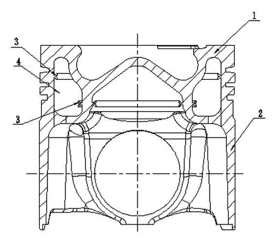
[0003] like figure 1 Shown is the existing friction welded forged steel piston, which is divided into a steel piston head 1 and a steel piston skirt 2. The steel piston head 1 and the steel piston skirt 2 are combined by friction welding to form a piston The internal cooling oil passage 4 is a common method for all-steel pistons at present, but this process makes the flange 4 of the friction weld occupy a large amount of space in the cooling oil passage
The friction welding flanging in the cooling oil passage will lead to the following serious problems: (1) Reduce the fluidity of the cooling oil in the inner cavity during operation, thereby reducing the cooling effect and increasing the risk of piston burning and cracking when the engine is working; (2) When the engine is working, the inner flanging falls off under the impact of high-pressure oil, forming hard particles, which will wear the key parts of the engine cylinder, reduce the engine power and worsen the emission

Method used


Image

  • Machining method of friction welding of forged steel piston
  • Machining method of friction welding of forged steel piston
  • Machining method of friction welding of forged steel piston

Examples


Embodiment

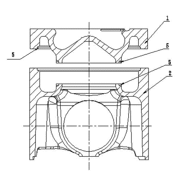
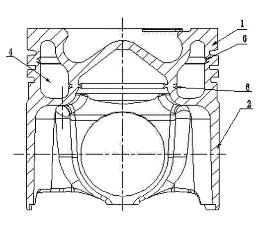
[0011] Embodiment: A kind of processing method of friction welding forged steel piston, concrete steps are as follows: (1), as shown in Figure 2, first steel piston is divided into piston head 1 and piston skirt 2, piston head and piston skirt Parts are mechanically processed to semi-finished products, in which the shape of the internal cooling oil passage on the piston head and piston skirt and the oil inlet and outlet are processed to the size of the finished product, leaving a margin of 1.5 to 4mm in the height direction. There is a gap 5 reserved on the side of the internal cooling oil channel at the welding surface; (2), then, if image 3 As shown in Fig. 1, the piston head 1 and the piston skirt 2 are friction welded into one, and the flanging 6 of the friction weld just fills the gap, and then the rest of the processing is performed on the piston.

[0012] As shown in Figure 4, the height H and width W of the reserved gap can be determined according to the width D of ...


PUM


Abstract

The invention provides a machining method of friction welding of a forged steel piston. The concrete steps are as follows: (1) dividing the steel piston into a piston head and a piston skirt which are respectively machined to be semi-finished products, wherein the shape of an inner cooling oil channel, an oil inlet and an oil outlet of the piston head and the piston skirt are machined to be in the sizes of a finished product, clearance of 1.5-4mm is reserved in the height direction, and a gap is reserved in the position, on one side of the inner-cooling oil channel, on the welding surface of the piston head and the piston skirt; and (2) combining the piston head and the piston skirt into a whole through the friction welding, wherein the gap is right filled with the turnup edge of a friction welding seam, and then carrying out other machining on the piston. The turnup edge is prevented from occurring on the inner side of the cooling oil channel, cooling effect of cooling oil on the top of the piston can not be affected, no turnup edges exist in the inner cooling oil channel, the weight of the piston can be reduced, the load of a connecting rod mechanism can be lightened, due to the fact that the turnup edge is embedded, the phenomenon that the inner turnup edge is scoured by the cooling oil to fall off to form hard particles, and risks including engine scraping and the like are caused is avoided.

Description

technical field [0001] The invention relates to a processing method of a friction welding forged steel piston, which is suitable for high horsepower and high load vehicle and marine engine steel pistons. Background technique [0002] In order to meet the requirement of increasing the explosion pressure of Euro V and Euro VI emission engines to above 20MPa, and the traditional aluminum piston has reached the limit of use, steel pistons must be used. [0003] like figure 1 Shown is the existing friction welded forged steel piston, which is divided into a steel piston head 1 and a steel piston skirt 2. The steel piston head 1 and the steel piston skirt 2 are combined by friction welding to form a piston The internal cooling oil passage 4 is a common method for all-steel pistons at present, but this process makes the flange 4 of the friction welding seam occupy a large amount of space in the cooling oil passage. The friction welding flanging in the cooling oil passage will lea...

Claims


Application Information

Patent Timeline
Patent Type & Authority Applications(China)
IPC IPC(8): F02F3/00
CPCF02F3/22F02F2003/0061
Inventor 岳济曹杰姜龙军王世伟
Owner DONGFENG PISTON & BEARING
Learn More