
Drilling tool and method for detecting reservoir stratum boundary and thickness while drilling

A drilling tool and boundary surface technology, which is applied in the field of geological exploration, can solve the problems such as the difficulty of the drilling tool to move forward, the inability to completely maintain the wellbore trajectory, and the inability to quantitatively measure it.

Active Publication Date: 2013-06-26
BC P INC CHINA NAT PETROLEUM CORP +2
View PDF4 Cites 13 Cited by
  • Summary
  • Abstract
  • Description
  • Claims
  • Application Information

AI Technical Summary

Problems solved by technology

[0002] At present, in order to obtain greater production capacity in the development of oil, natural gas and coalbed methane, horizontal well drilling technology is often used to keep the wellbore trajectory drilled by the drilling rig in the oil and gas layer and coal seam, but the wellbore trajectory cannot be achieved in actual construction. It is completely kept in the oil-gas layer and coal seam. The reason is that there is no method and technology that can quantitatively measure the interface and thickness of the oil-gas layer and coal seam. However, this is only a qualitative judgment and cannot quantitatively or relatively accurately measure the distance between the wellbore trajectory and the upper and lower boundaries. The deeper the wellbore is, the more difficult it is for the drilling tool to drill forward. Therefore, the depth of the horizontal well is limited, and the wellbore trajectory cannot be kept at the position of the high-yield zone, which greatly affects the productivity of a single well.

Method used


Image

  • Drilling tool and method for detecting reservoir stratum boundary and thickness while drilling
  • Drilling tool and method for detecting reservoir stratum boundary and thickness while drilling
  • Drilling tool and method for detecting reservoir stratum boundary and thickness while drilling

Examples


Embodiment Construction

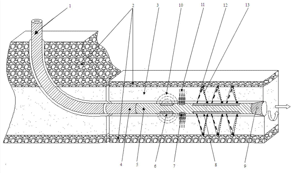
[0024] A drilling tool mainly includes drill rods, screw motors and drill collars connected in sequence, and also includes dielectric constant measuring probes installed on the upper and lower sides of the drill collar, and natural gamma ray probes installed on the upper and lower sides of the drill collar. A sensor, an electromagnetic wave transmitting source and a receiving antenna installed on the upper and lower sides of the drill collar.

[0025] Wherein, the dielectric constant measuring probes installed on the upper and lower sides of the drill collar are natural gamma ray sensors installed on the upper and lower sides of the drill collar for judging and identifying the lithology of the formation where the drilling tool is located.

[0026] Among them, the drill collar equipped with ultra-high frequency electromagnetic wave and microwave emission source, receiving antenna, gamma sensor and dielectric constant measuring probe is arranged near the drill bit before the scre...


PUM


Abstract

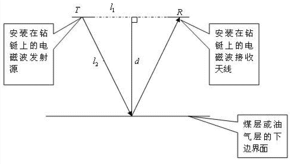
The invention discloses a drilling tool and a method for detecting the reservoir stratum boundary and thickness while drilling. In the horizontal drilling wells of coal stratums, hydrocarbon reservoir and other reservoir stratums, an ultrahigh-frequency electromagnetic wave and microwave reflection stratum detection ranging method is applied to identify the coal stratums, hydrocarbon reservoir and other reservoir stratums and the boundaries of upper and lower overlaying stratums thereof and measure the distances between a horizontal drill and the boundaries of upper and lower overlaying stratums. When the ground trenchless construction horizontal drilling operation is carried out on the basis of the method, obstacles above and below a track of a horizontal shaft can be detected, and the distances between the horizontal shaft and the obstacles can be measured; and when the horizontal drilling operation which passes through rivers or buildings is carried out on the basis of the method, a distance between a river bed or a building foundation and the shaft below the river bed or the building foundation is detected, and the drill is kept parallel to the river bed or the building foundation or within a preset distance in a drilling process.

Description

technical field [0001] The invention belongs to the field of geological exploration, and in particular relates to a drilling tool and a method for detecting the interface and thickness of coal seams and oil and gas reservoirs while drilling downhole. Background technique [0002] At present, in order to obtain greater production capacity in the development of oil, natural gas and coalbed methane, horizontal well drilling technology is often used to keep the wellbore trajectory drilled by the drilling rig in the oil and gas layer and coal seam, but the wellbore trajectory cannot be achieved in actual construction. It is completely kept in the oil-gas layer and coal seam. The reason is that there is no method and technology that can quantitatively measure the interface and thickness of the oil-gas layer and coal seam. However, this is only a qualitative judgment and cannot quantitatively or relatively accurately measure the distance between the wellbore trajectory and the uppe...

Claims


Application Information

Patent Timeline
Patent Type & Authority Applications(China)
IPC IPC(8): E21B49/00
Inventor 邹来方盛利民李林窦修荣张明宝滕鑫淼石荣
Owner BC P INC CHINA NAT PETROLEUM CORP
Learn More