Eureka AIR delivers breakthrough ideas for toughest innovation challenges, trusted by R&D personnel around the world.

Method for Constructing Geologic Models of Subsurface Sedimentary Volumes

a geologic model and subsurface sediment technology, applied in the field of geologic modeling, can solve the problems of inability to accurately characterize the identification or modeling of channels, inability to readily capture complex spatial information provided by simple shapes provided in existing methods, and inability to closely replicate structures observed in depositional systems such as rivers, deltas and deep-water canyons and fans

Active Publication Date: 2009-08-13
VAN WAGONER JOHN C +7
View PDF29 Cites 56 Cited by
  • Summary
  • Abstract
  • Description
  • Claims
  • Application Information

AI Technical Summary

Problems solved by technology

The chief drawback to geocellular models is that they generally do not closely replicate structures observed in depositional systems such as rivers, deltas and deep-water canyons and fans.
The simple shapes provided in existing methods can not readily capture the complex spatial information seen in modern three-dimensional seismic surveys.
While channelized systems are significant hydrocarbon reservoir types, the identification or modeling of channels is incomplete without accurately characterizing the potentially porous and permeable sands that fill them.
Process-based models can typically generate realistic-looking simulated deposits, but they are not commonly used for commercial geologic modeling because it is difficult to adjust the model inputs in such a way as to cause the simulated deposit to honor subsurface data constraints.
Unlike geocellular or object-based models, process-based models typically cannot be efficiently optimized by computer algorithms when new static or dynamic data become available.
Finally, modern three-dimensional seismic surveys provide a spatial framework for geologic models which is difficult to replicate with process-based models.

Method used


Image

  • Method for Constructing Geologic Models of Subsurface Sedimentary Volumes
  • Method for Constructing Geologic Models of Subsurface Sedimentary Volumes
  • Method for Constructing Geologic Models of Subsurface Sedimentary Volumes

Examples


first embodiment

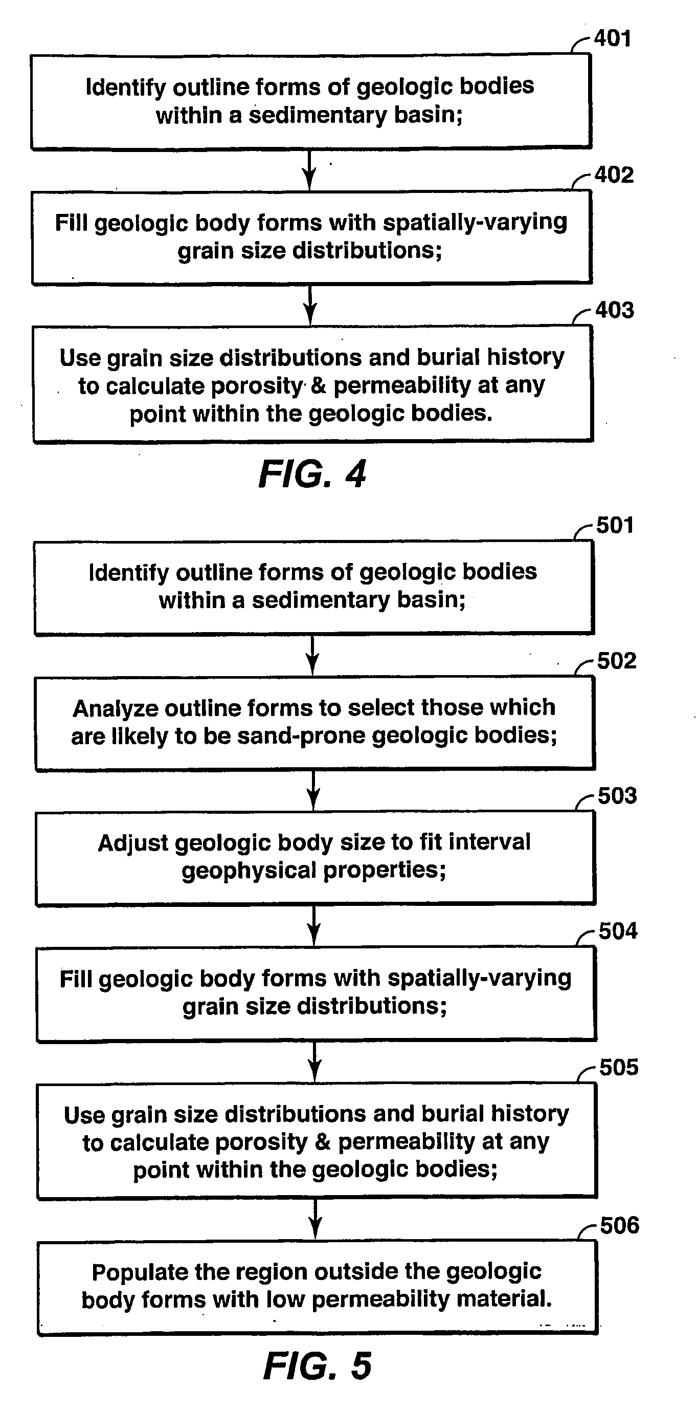
[0036]A first embodiment will now be described. With reference to FIG. 4, this embodiment involves procedures to determine rock properties within a subsurface region using a seismic image of the region. As illustrated in FIG. 4, an outline form of at least one geologic body within the subsurface region is identified (step 401). The grain-size distribution in at least one point within the geologic bodies as identified in step 401 is determined (step 402). Finally, at least one rock property is determined using the grain size distribution found in step 402 (step 403). The rock properties include porosity and permeability. The individual steps will be described in greater detail in the following paragraphs.

[0037]Step 401 is identification of outline forms of geologic bodies and can be accomplished by a variety of known methods from geologic data. The geologic data can include but is not limited to seismic data, outcrop data or studies, core samples, reservoir performance data and / or we...

second embodiment

[0055]A second embodiment will now be described. With reference to FIG. 5, this embodiment involves procedures to determine rock properties within a subsurface region using a seismic image of the region. As illustrated in FIG. 5, outline forms of geologic bodies within the reservoir interval are identified (step 501). Each outline form is evaluated and discarded if it is determined that the form is unlikely to be a sand-prone geologic body (step 502). The outline forms are adjusted in size to make them consistent with additional constraints on the reservoir (step 503). The grain-size distribution at any point within the geologic body forms is determined (step 504). The rock properties are determined using the grain size distribution (step 505). The volume within the reservoir interval that is not associated with a geologic body form is filled with low permeability material (step 506).

[0056]Step 501 involves the identification of the outline forms of geologic bodies from geologic dat...

third embodiment

[0070]In addition to the embodiments described above, a third embodiment is further described in FIG. 12. With reference to FIG. 12, this embodiment involves procedures to determine rock properties within a subsurface region using a seismic image of the region. As illustrated in FIG. 12, an outline form of at least one geologic body within the subsurface region is identified in step 1201. The depositing flow field that created the geologic body is determined from the outline form of the body in step 1202. The grain size distribution within the geologic body is determined using a relationship between the estimated flow field and the deposited grain size distribution in step 1203. Then, rock properties within the geologic body are determined based on the estimated grain size distribution in step 1204.

[0071]Step 1201 is the identification of outline forms of geologic bodies and may be accomplished according to a variety of methods, as described in step 401.

[0072]Step 1202 involves dete...


PUM


Abstract

A method is disclosed for using a three-dimensional seismic image of a subsurface earth volume to construct a geologic model specifying the spatially-varying grain size distribution, porosity, and permeability throughout the volume. The method applies to earth volumes composed of water-lain clastic sedimentary deposits and involves, in one embodiment, (a) identifying the outline forms of geologic bodies in geologic data; (b) using the outline forms of the geologic bodies to determine the spatially-varying grain size distribution within the bodies, guided by assumptions about the nature and behavior of the paleoflow that deposited the bodies; (c) determining rock properties such as, porosity and permeability within the geologic bodies based on grain-size distribution, mineralogy and burial history information.

Description

CROSS RELATED APPLICATIONS[0001]This application claims priority to U.S. Provisional Application No. 60 / 609,057, which was filed on Sep. 10, 2004.FIELD OF THE INVENTION[0002]This invention relates generally to the field of geologic modeling. Specifically, the invention is a method for constructing a model of geologic properties throughout a subsurface volume.BACKGROUND OF THE INVENTION[0003]A geologic model is a computer-based representation of a subsurface earth volume, such as a petroleum reservoir or a depositional basin. In the oil and gas industry, geologic models are commonly used in activities such as determining the locations of wells, estimating hydrocarbon reserves, or planning reservoir-development strategies. Geologic models are commonly inputs to production flow simulations that are used to test development and production scenarios in order to optimize return on investment. A key parameter in flow simulation is the spatial distribution of permeability, which together wi...

Claims


Application Information

Patent Timeline
Patent Type & Authority Applications(United States)
IPC IPC(8): G06T17/20G06G7/50
CPCG01V2210/661G01V1/282
Inventor VAN WAGONER, JOHN C.DUNN, PAUL A.DEFFENBAUGH, MAXAWWILLER, DAVID N.SUN, TAOLI, DACHANGHOYAL, DAVID C.DONOFRIO, CHRIS J.
Owner VAN WAGONER JOHN C
Why Eureka
Eureka Blog
Learn More