Limiting pressing sliding rod

A sliding rod and push-up technology, applied in the direction of hoisting devices, can solve the problems of single function and poor adaptability, and achieve the effects of broad market space, simple manufacturing, high application value and economic added value.

Inactive Publication Date: 2013-06-26
钟婕
View PDF4 Cites 0 Cited by
  • Summary
  • Abstract
  • Description
  • Claims
  • Application Information

AI Technical Summary

Problems solved by technology

[0008] The purpose of the present invention is to overcome the defects of single function and poor adaptability of the known screw abutting rods, and provide the public with a unique helical abutting sliding rod.

Method used


Image

  • Limiting pressing sliding rod
  • Limiting pressing sliding rod
  • Limiting pressing sliding rod

Examples


Embodiment Construction

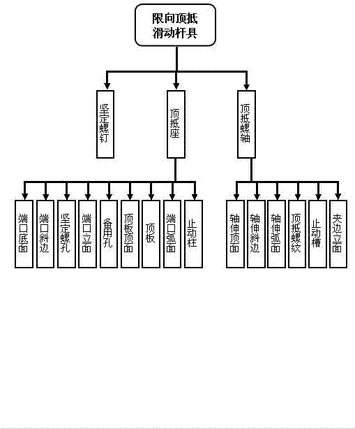
[0031] As a technical solution, the present invention can be implemented through the organic combination of corresponding parts. The organizational structure of the product of the present invention is as figure 1 shown.

[0032] figure 1 Among them, the product is composed of three parts: set screw, abutting seat, and abutting screw shaft. The structure of each part includes its own different components. There are nine components: screw hole, port elevation, spare hole, top plate top surface, top plate, port arc surface, and stopper column; the structure of the part that resists the screw shaft includes the top surface of the shaft extension, the hypotenuse of the shaft extension, the arc surface of the shaft extension, It consists of six parts: abutment screw thread, stop groove, clamping edge elevation.

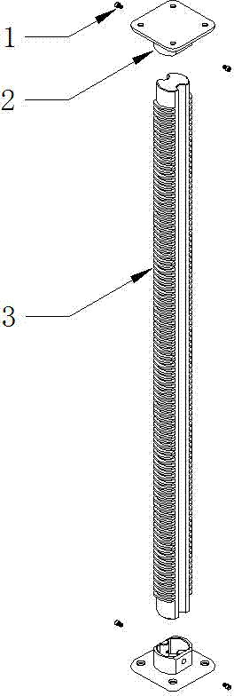
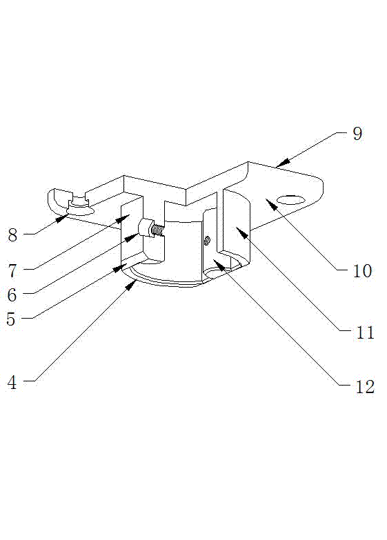
[0033] In the embodiment, the appearance of each part of the product is as follows figure 2 shown.

[0034] figure 2 , the parts arranged in the order of labels are...


PUM


Abstract

The invention relates to a pressing rod and in particular relates to a sliding pressing device which adopts spiral telescopic shift and strictly limits the pressing rod to rotate around the axis. The product consists of three parts, namely a fastening screw, a pressing seat and a pressing screw shaft, and comprises fifteen parts, namely a port bottom surface, a port bevel edge, a fastening screw hole, a port facade, a spare hole, a top plate top surface, a top plate, a port arc surface, a stop post, a shaft extension top surface, a shaft extension bevel edge, a shaft extension arc surface, a top pressed thread, a stop groove and a clamping side facade. The defects that the known pressing rod is large in size, rotates around the axis and radially moves, is unbalanced in use and the like are overcome, and the sliding pressing device with the excellent characteristics of being capable and vigorous in structure, balanced, stable, wide in adaptability and the like is formed. In addition, the device has the advantages of simpleness in implementation and easiness and convenience in manufacturing, and the formed product is attractive in appearance, firm and durable and wide in market space and has high social application values and economic additional values.

Description

technical field [0001] The invention relates to a resisting pole, in particular to a sliding jacking device which not only adopts spiral telescopic movement but also strictly restricts the pivoting rotation of the resisting pole. Background technique [0002] Currently known abutment rods used in screw abutment devices generally have the following defects: [0003] ⑴ Large volume—the currently known screw abutting rods are often formed by connecting two parts of a threaded column and a sliding column in series, and the abutting distance is limited by both the length of the threaded column and the length of the sliding column; Under the premise that the abutting distance is equal, the total length of the known helical abutting rod appears lengthy and the volume is relatively large. [0004] ⑵ Rotation around the axis——The known helical abutment rods often rotate around the axis during use, which is difficult to meet the needs of specific pushing and abutting operations. [...

Claims


Application Information

Patent Timeline
IPC IPC(8): B66F3/08
Inventor 钟婕
Owner 钟婕
Why Eureka
Try Eureka