Method for manufacturing contact terminal, contact terminal manufacturing apparatus, and contact terminal

一种接触端子、接触部分的技术,应用在制造工具、接触部件、接触件制造等方向,能够解决增加制造成本等问题

Inactive Publication Date: 2013-06-26
DENSO CORP +1
View PDF8 Cites 2 Cited by
  • Summary
  • Abstract
  • Description
  • Claims
  • Application Information

AI Technical Summary

Problems solved by technology

This increases manufacturing costs

Method used


Image

  • Method for manufacturing contact terminal, contact terminal manufacturing apparatus, and contact terminal
  • Method for manufacturing contact terminal, contact terminal manufacturing apparatus, and contact terminal
  • Method for manufacturing contact terminal, contact terminal manufacturing apparatus, and contact terminal

Examples


Embodiment Construction

[0028] Referring to the accompanying drawings, an embodiment according to the present invention will be described below.

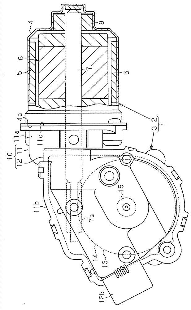
[0029] figure 1 It is a diagram of a motor 1 of this embodiment, which is used as a driving source of a car wiper device, and the car wiper device can wipe water such as raindrops from the windshield of a car. The motor 1 includes a motor unit 2 that generates rotation, and a reduction gear unit 3 that reduces the speed of rotation generated by the motor unit 2 and outputs the rotation.

[0030] The motor unit 2 includes a cylindrical yoke case 4 having a closed end and two pairs (four in total) of magnets 5 fixed to the inner peripheral surface of the yoke case 4 . Each pair of magnets 5 is opposite in the radial direction of the yoke housing 4 . A rotatable armature 6 is disposed inside the two pairs of magnets 5 . The armature 6 comprises a rod-shaped rotating shaft 7 having a base supported by a bearing 8 provided in the yoke housing 4 in the cente...


PUM


Abstract

The present invention relates to a method for manufacturing a contact terminal including a contact portion that slides against a surface of a conductive contact plate. The manufacturing method includes forming a projection in a metal plate by performing a drawing process, wherein the projection projects in a thicknesswise direction of the metal plate and has a larger diameter than the contact portion. The manufacturing method further includes forming the contact portion from the projection by performing a contraction pressing process at least once on the projection so that the diameter of the projection gradually decreases, while the height of the projection remains the same or decreases in a stepwise manner.

Description

technical field [0001] The invention relates to a method for producing a contact terminal sliding against a contact plate, a device for producing a contact terminal and a contact terminal. Background technique [0002] A motor as a driving source for an automobile wiper device includes a motor unit and a reduction gear unit, which are integrally coupled to each other. When power is supplied to the motor unit, the motor unit rotates and drives the rotating shaft. The reduction gear unit may reduce the rotation speed generated by the motor unit. The reduction gear unit accommodates a worm wheel forming a reduction gear mechanism and an output shaft integrally rotating with the worm wheel. A linkage connects the output shaft to the wiper blades. [0003] In such a motor, when the wiper switch is turned off to stop the wiping action of the wiper, the wiper will continue to move to reach a predetermined stop position before stopping. In order to supply power to the motor unit...

Claims


Application Information

Patent Timeline
Patent Type & Authority Applications(China)
IPC IPC(8): B60S1/08
CPCH01R43/16B21D22/20B21D37/08H01R13/02Y10T29/49218
Inventor 山木孝郎村上精一浜中武
Owner DENSO CORP
Why Eureka
Try Eureka