An engine intake pipe clamp

An air intake pipe and engine technology, applied in clamping, manufacturing tools, metal processing mechanical parts, etc., can solve the problems of inability to effectively fix irregular items, manual manual clamping, etc., and achieve convenient adjustment of the horizontal position of the workpiece and convenient processing. Processing, high work efficiency

Inactive Publication Date: 2015-09-02
繁昌县金牛机械铸造有限责任公司
View PDF6 Cites 0 Cited by
  • Summary
  • Abstract
  • Description
  • Claims
  • Application Information

AI Technical Summary

Problems solved by technology

[0003] In order to overcome the shortage that the existing clamps cannot effectively fix irregular objects and require manual clamping, the present invention provides a clamp, which can effectively fix the engine intake pipe and facilitate the processing of the bottom surface

Method used


Image

  • An engine intake pipe clamp
  • An engine intake pipe clamp
  • An engine intake pipe clamp

Examples


Embodiment Construction

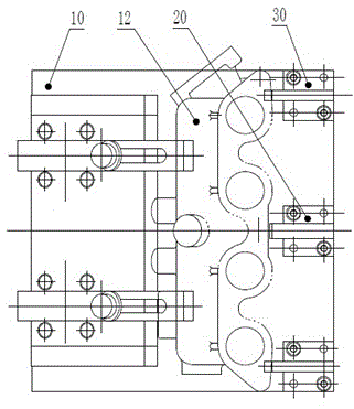
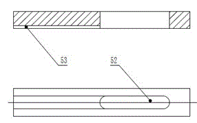
[0011] like figure 1 figure 2 As shown, the invention is composed of a clamp body 10, a positioning seat 20, a positioning block 30, a pressure cylinder 40, and a pressure plate 50. The bottom of the positioning block 30 is fixed on the clamp body 10 through a taper pin hole of a bolt, and the positioning seat 20 is fixed by threaded connection. At the midpoint of the two positioning blocks 30, the taper pin hole at the joint is used for assembly. Pressing plate 50 constitutes clamping device together with support rod 51, spring 54, pressure cylinder 40, and pressing plate 50 is connected on the panel 11 of clamping body 10 by supporting rod 51, spring 54, and panel 11 is with clamping body 10 bottom plate when processing as required. The included angle can be any angle from 0 to 90 degrees. A pair of pressure cylinders 30 are symmetrically distributed front and back under the panel 11 of the clamp body 10, and the push rod 41 passes through the hinged hole on the panel 11 ...


PUM


Abstract

The invention relates to a special fixture capable of stably clamping an air inlet pipe of an engine. The fixture is composed of a locating block, a locating seat, a fixture body, a pressure cylinder and a press board in a combined mode, wherein pressing force is provided by the pressure cylinder, and the horizontal position of a workpiece can be freely adjusted through the locating seat. The air inlet pipe of the engine can be stably clamped to facilitate processing of the bottom surface, the same position of the workpiece is clamped every time, and the pressing force is provided by the pressure cylinder, so that working efficiency is high, the structure is simple, clamping operation is convenient, the fixture is long in service life, and stability of the workpiece is high. The fixture can achieve effective and fixed clamping of the air inlet pipe of the engine and other irregular workpiece.

Description

technical field [0001] The invention relates to a mechanical processing equipment, in particular to a special clamp capable of stably clamping an engine intake pipe. Background technique [0002] Currently known fixtures are composed of positioning elements, clamping devices, indexing devices, connecting elements, and clamp bodies. The fixtures use the principle of levers. The force arm on the side of the center point is multiplied by the force acting on the force arm. It is equal to the length of the force arm on the other side multiplied by the force acting on the clamped item, and the clamped item is fixed by the pressure of the clamping device. However, the single structure of the traditional fixture is mainly aimed at objects with relatively regular geometric shapes. The clamping force is applied manually, so it is difficult to achieve reliable fixation with ordinary fixtures, which will cause the engine intake pipe to fall off and be damaged during processing. Conten...

Claims


Application Information

Patent Timeline
Patent Type & Authority Patents(China)
IPC IPC(8): B23Q3/08
Inventor 杨国太杨向东杨丹玥
Owner 繁昌县金牛机械铸造有限责任公司
Why Eureka
Try Eureka