
Tube expanding method and tube expanding device for expanding connection of multiple tubes and tube plates

A tube expansion device and tube technology, which is applied in the field of shell-and-tube/tube-fin heat exchangers and machinery, can solve the problems of long labor hours, high manufacturing labor cost, long occupation time, etc., and achieves low dimensional accuracy requirements and production. The effect of high efficiency and convenient operation

Active Publication Date: 2013-06-26
ZHEJIANG YINLUN MACHINERY
View PDF7 Cites 12 Cited by
  • Summary
  • Abstract
  • Description
  • Claims
  • Application Information

AI Technical Summary

Problems solved by technology

[0002] Shell-tube / fin-tube heat exchangers are an important structural type in the field of heat exchangers. The connection of tubes and tube sheets is one of the most important processes in the manufacture of shell-tube / fin-tube heat exchangers. , this process usually uses a single tube and tube sheet expansion process one by one, so the expansion process consumes a lot of man-hours, the proportion of manual work is heavy, the worker's skill requirements and operation intensity are high, and the process processing and production efficiency is low. In the entire product manufacturing cycle It takes a long time, and the cost of product manufacturing hours is high, which is not conducive to the improvement of mass production efficiency of products, and cannot meet the needs of modern large-scale production

Method used


Image

  • Tube expanding method and tube expanding device for expanding connection of multiple tubes and tube plates
  • Tube expanding method and tube expanding device for expanding connection of multiple tubes and tube plates
  • Tube expanding method and tube expanding device for expanding connection of multiple tubes and tube plates

Examples


Embodiment Construction

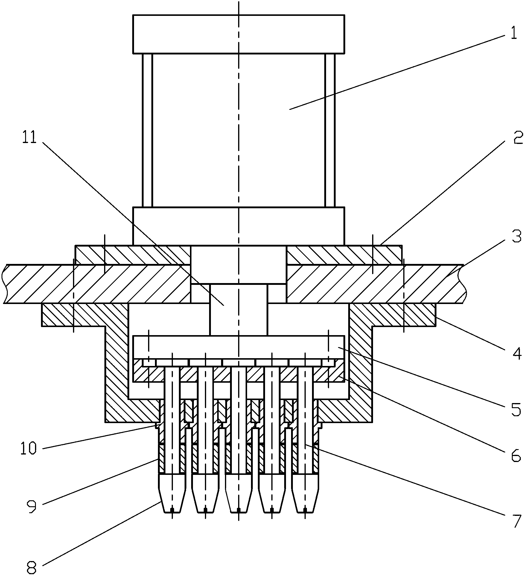
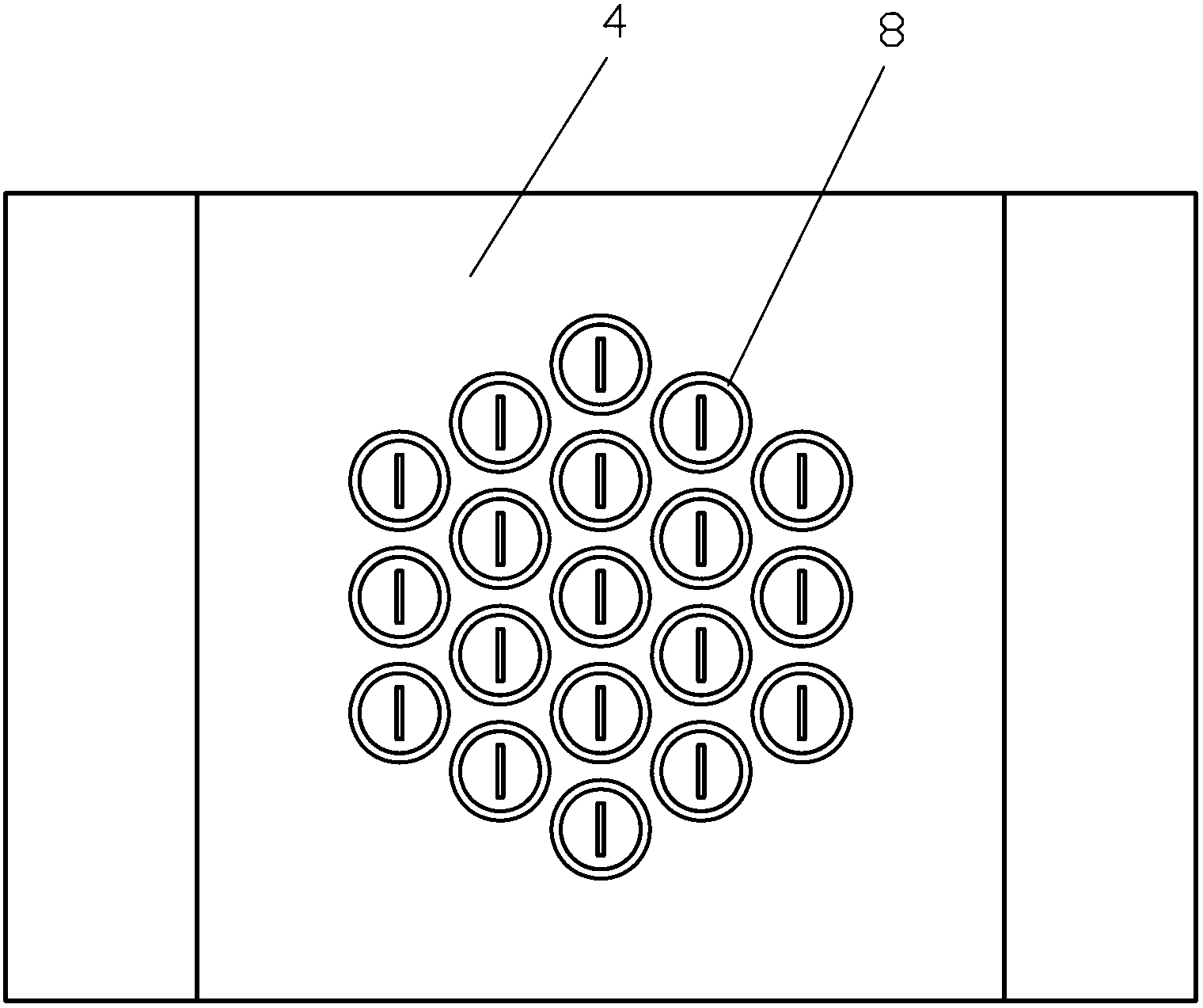
[0017] refer to figure 1 and figure 2 , a tube expansion device of the present invention, including an expansion head tie rod seat 6, an expansion joint seat 4, an expansion head assembly, a fixed plate 3 and a hydraulic cylinder connecting plate 5, and the expansion head assembly includes a plurality of expansion head tie rods 7, The upper end of the expansion head rod 7 is set on the expansion head rod seat 6, and each expansion head rod 7 is sequentially set with an expansion rod bushing 10, an elastic expansion sleeve 9 and a guide nut 8; The bushing 10 is fixed in the bottom through hole of the expansion joint seat 4, and the upper part of the expansion joint seat 4 is connected to the cylinder block 1 of the hydraulic cylinder through the fixed plate 3; the expansion head tie rod seat 6 is passed through The hydraulic cylinder connecting plate 5 is connected to the hydraulic cylinder tie rod 11 .

[0018] The present invention carries out tube expansion according to t...


PUM


Abstract

The invention discloses a tube expanding device which comprises an expanding head draw bar seat, an expanding connection seat, an expanding head component, a fixing plate and a hydraulic cylinder connecting plate. The tube expanding device is characterized in that the expanding head component comprises a plurality of expanding head draw bars. The upper ends of the expanding head draw bars are arranged on the expanding head draw bar seat. An expanding bar lining sleeve, an elastic expanding sleeve and a guide nut are sequentially sleeved on each expanding draw bar. Each expanding bar lining sleeve is fixed in a through hole in the bottom of the expanding connection seat. The upper portion of the expanding connection seat is connected with a cylinder body of a hydraulic cylinder through the fixing plate. The expanding head draw bar seat is connected with a hydraulic cylinder draw bar through the hydraulic cylinder connecting plate. The tube expanding device for expanding connection of multiple tubes and tube plates is simple in structure, convenient to operate, low in product part size accuracy requirement, high in production efficiency, capable of conducting one end expanding connection and two end expanding connection and applicable to direct adhering tube expanding technology and pre-expanding technology before welding.

Description

technical field [0001] The present invention relates to the field of machinery, in particular to the field of shell-and-tube / fin-type heat exchangers, in particular to the expansion joint of multiple tubes and tube-sheets during the manufacturing process of shell-and-tube / fin-type heat exchangers. Tube process method and tube expansion device. technical background [0002] Shell-tube / fin-tube heat exchangers are an important structural type in the field of heat exchangers. The connection of tubes and tube sheets is one of the most important processes in the manufacture of shell-tube / fin-tube heat exchangers. , this process usually uses a single tube and tube sheet expansion process one by one, so the expansion process consumes a lot of man-hours, the proportion of manual work is heavy, the worker's skill requirements and operation intensity are high, and the process processing and production efficiency is low. In the entire product manufacturing cycle It takes a long time, ...

Claims


Application Information

Patent Timeline
Patent Type & Authority Applications(China)
IPC IPC(8): B21D39/20B21D53/08
Inventor 胡永明
Owner ZHEJIANG YINLUN MACHINERY
Learn More