
Device for eliminating laser radar speed measuring zero point

A laser radar and velocity measurement technology, applied in the coupling of optical waveguides, radio wave measurement systems, instruments, etc., can solve the problems of reducing beat frequency efficiency, mismatch of spatial angle between echo light and local oscillator light, and difficulty in extracting beat frequency signals. , to achieve the effect of improving the beat frequency efficiency

Inactive Publication Date: 2014-12-03
BEIHANG UNIV
View PDF3 Cites 0 Cited by
  • Summary
  • Abstract
  • Description
  • Claims
  • Application Information

AI Technical Summary

Problems solved by technology

[0006] The second laser Doppler speed measuring radar with an all-fiber structure in the prior art has the disadvantages of its optical path structure: although the optical path structure strictly controls the polarization of the local oscillator light and signal light, it cannot When the polarization state of the signal light changes greatly due to complex conditions, there will be a serious spatial angle mismatch between the echo light and the local oscillator light at the beat frequency
This will greatly reduce the beat frequency efficiency, making it difficult to extract the beat frequency signal

Method used


Image

  • Device for eliminating laser radar speed measuring zero point
  • Device for eliminating laser radar speed measuring zero point
  • Device for eliminating laser radar speed measuring zero point

Examples


Embodiment Construction

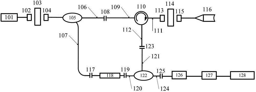
[0035] Such as figure 1 As shown, the present invention includes: a polarization maintaining laser 101, a first flange 103, a 2×2 polarization maintaining coupler 105, a single-mode circulator 110, a second flange 114, an elliptical core fiber 118, a 2×2 single Mode coupler 122, photodetector 126, PXI acquisition card 127 and computer 128.

[0036]The polarization-maintaining laser 101 is used to generate linearly polarized light with a power of 10 mW and a wavelength of 1.55 μm. The pigtail fiber of the polarization-maintaining laser 101 is a panda-shaped polarization-maintaining fiber, and the linearly polarized light propagates along the fast axis of the panda-shaped polarization-maintaining fiber; the polarization-maintaining laser The first FC / APC connector 102 attached to the pigtail 101 is a polarization-maintaining FC / APC connector. ) connector exiting the fast axis.

[0037] The first flange 103 is used to connect the first FC / APC joint 103 and the second FC / APC joi...


PUM


Abstract

The invention discloses a device for eliminating a laser radar speed measuring zero point. The device comprises a polarization-preserving laser, a first flange plate, a 2*2 polarization-preserving coupler, an elliptic core polarization-preserving fiber, a single-mode circulator, a second flange plate, a polarization-preserving collimator, a 2*2 single-mode coupler, a photoelectric detector, a PXI (PCI extensions for instrumentation) acquisition card and a computer. The elliptic core polarization-preserving fiber and the 2*2 polarization-preserving coupler are welded as required to achieve the effect of a lambda / 4 fiber wave plate, local oscillation light passing through the elliptic core polarization-preserving fiber is changed from linear polarized light into circular polarized light, the speed is prevented from suddenly being zero due to mismatch of the local oscillation light and the polarization state of an echo light in the speed measuring process, and beat frequency efficiency is improved.

Description

technical field [0001] The invention belongs to the field of Doppler laser radar speed measurement, in particular to a device for eliminating the zero point of laser radar speed measurement. Background technique [0002] Laser Doppler speed measurement technology has developed rapidly in recent years and is widely used in many fields such as military affairs, aerospace and industrial production. The detection forms of laser Doppler velocimetry can be divided into direct detection and coherent detection. Coherent detection technology has become the mainstream detection scheme due to its high detection accuracy and easy integration. With the rapid development of fiber optic technology, fiber laser technology has gradually matured. The laser Doppler coherent velocimetry system with all-fiber structure has the advantages of high coherence efficiency, simple optical path adjustment, system stability and high degree of integration. [0003] The first laser Doppler speed measurin...

Claims


Application Information

Patent Timeline
Patent Type & Authority Patents(China)
IPC IPC(8): G01S7/481G02B6/255
Inventor 林志立邬占军韩凤山范哲孙鸣捷欧攀张春熹
Owner BEIHANG UNIV
Learn More