
Photoelectric encoder rotating pulse display device

A technology of photoelectric encoder and display device, which is applied in the direction of measuring device, instrument, measurement value indicator, etc., can solve the problem of not considering the rotation angle and rotation direction of the photoelectric encoder, increasing hardware cost, software complexity, software portability and poor plasticity and other problems, to achieve the effect of simple and clear algorithm, strong versatility, and hardware cost saving

Inactive Publication Date: 2013-06-19
CHONGQING UNIV
View PDF4 Cites 12 Cited by
  • Summary
  • Abstract
  • Description
  • Claims
  • Application Information

AI Technical Summary

Problems solved by technology

[0003] In the current engineering application, the operation of the stepper motor usually needs to be controlled by a photoelectric encoder. In the process of the encoder controlling the rotation of the stepper motor, the encoder is required to rotate at a certain angle, and the corresponding stepper motor rotates at a certain angle. However, due to At present, most of the parameters such as the rotation angle are identified and operated manually, and the numbers are not automatically displayed, and misoperations are prone to occur, such as excessive motor wear caused by excessive rotation, exceeding the required angle, etc.
[0004] Most of the currently existing photoelectric encoder pulse display devices or methods are controlled by single-chip microcomputers. Compared with FPGAs, single-chip microcomputers require a large number of peripheral circuit drivers, which increases hardware costs and software complexity on the one hand, making software portability and plasticity poor. , on the other hand, it also makes the scalability of the device poor and the processing speed slow
At the same time, the current display device simply counts the output pulses without considering the rotation angle and direction of the photoelectric encoder, which makes it easy to cause misoperation during use

Method used


Image

  • Photoelectric encoder rotating pulse display device

Examples


Embodiment Construction

[0016] The preferred embodiments of the present invention will be described in detail below with reference to the accompanying drawings.

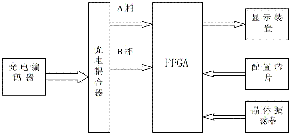
[0017] figure 1 It is a structural schematic diagram of the present invention, the photoelectric encoder rotary pulse display device includes a photoelectric coupler, a field programmable gate array FPGA, a crystal oscillator, a configuration chip and a display device; the photoelectric coupler receives the photoelectric encoder The output AB two-phase pulse signal is amplified and then output to the field programmable gate array FPGA. FPGA calculates the rotation direction, rotation angle and pulse number of the photoelectric encoder according to the received pulse signal, and transmits the calculation result To the display device for display, in this embodiment, the display device uses 8-segment LED digital tubes; the configuration chip is used to store the algorithm program of the FPGA, and the crystal oscillator is used to provide the c...


PUM


Abstract

The invention discloses a photoelectric encoder rotating pulse display device, and belongs to the application field of photoelectric encoder measuring. The photoelectric encoder rotating pulse display device comprises a photoelectric coupler, a field-programmable gate array (FPGA), a crystal oscillator, a configured chip and a display device. The photoelectric coupler receives and amplifies AB two-phase pulse signals which are outputted by a photoelectric encoder, and then outputs the two-phase pulse signals to the FPGA. The FPGA calculates according to the received pulse signals to obtain the rotating direction, the rotating angle and the number of pulses of the photoelectric encoder, and transmits the calculated results to the display device. The configured chip is used for storing the algorithmic routine of the FPGA. The crystal oscillator is used for providing clock signals. The photoelectric encoder rotating pulse display device does not need to be driven by a large number of peripheral circuits, so that hardware cost can be saved, and transportability and expansibility are high. Meanwhile, the photoelectric encoder rotating pulse display device can display not only the pulse count but also the rotating angle so as to avoid a man-made wrong operation.

Description

technical field [0001] The invention belongs to the application field of photoelectric encoder measurement, and relates to a photoelectric encoder rotary pulse display device. Background technique [0002] Photoelectric encoder is a sensor that converts the mechanical geometric displacement on the output shaft into pulse or digital quantity through photoelectric conversion, and is currently the most widely used sensor. The role of the photoelectric encoder in the motion control system is to convert parameters such as position and angle into digital quantities. The rotary encoder is a device used to measure the rotational speed. It is divided into two types: single output and dual output. [0003] In the current engineering application, the operation of the stepper motor usually needs to be controlled by a photoelectric encoder. In the process of the encoder controlling the rotation of the stepper motor, the encoder is required to rotate at a certain angle, and the correspond...

Claims


Application Information

Patent Timeline
IPC IPC(8): G01D7/00
Inventor 高富强严强安康李岭兰扬陈赟飞冯永
Owner CHONGQING UNIV
Learn More