Vacuum heat insulation material, a heat insulation box employing the vacuum heat insulation material, equipment employing the vacuum heat insulation material, and a method of making the vacuum heat insulation material
A technology of vacuum heat insulation material and heat insulation material, which is applied in the direction of heat exchange equipment, lighting and heating equipment, mechanical equipment, etc., to achieve the effect of improved heat insulation effect, improved heat insulation performance, and no reduction in thickness
- Summary
- Abstract
- Description
- Claims
- Application Information
AI Technical Summary
Problems solved by technology
Method used
Image
Examples
Embodiment approach 1
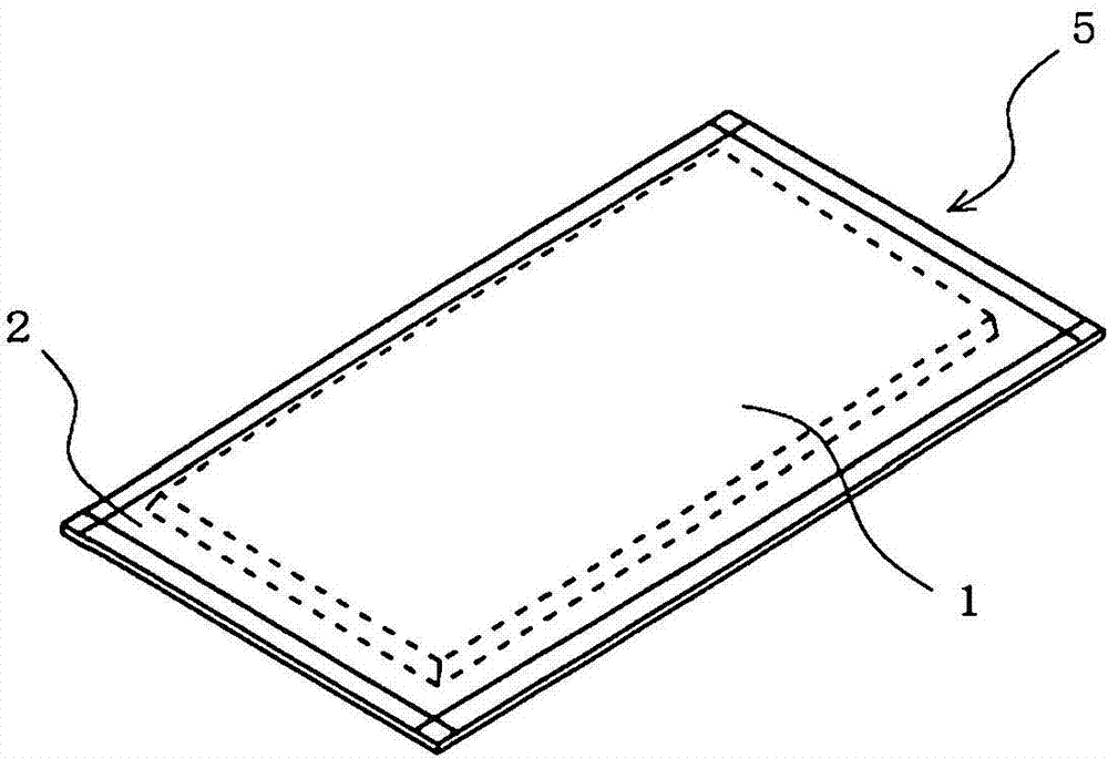
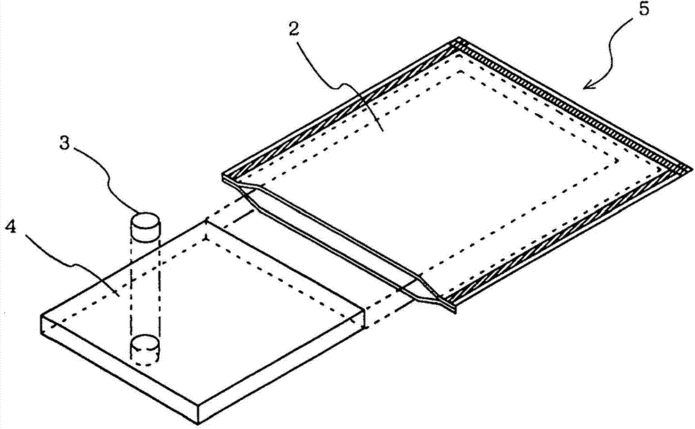
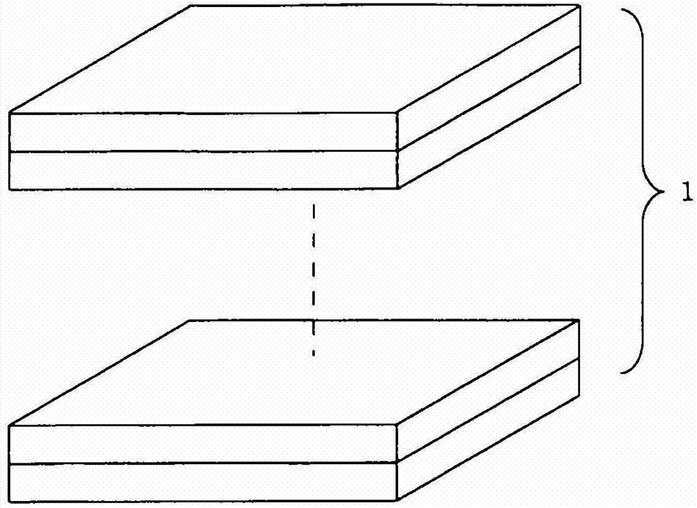
[0053] figure 1 It is a perspective view which shows the vacuum heat insulating material before groove formation concerning Embodiment 1 of this invention. figure 2 It is an exploded perspective view of the vacuum heat insulating material before groove formation according to Embodiment 1 of the present invention. image 3 It is explanatory drawing of the laminated state of the core material of the vacuum heat insulating material concerning Embodiment 1 of this invention.
[0054] The vacuum heat insulating material 5 before groove formation according to Embodiment 1 of the present invention is as follows: figure 1 as well as figure 2 In this way, the outer covering material 2 having air-shielding gas barrier properties, the core material 4 and the gas adsorbent 3 sealed in the outer covering material 2 are included, and the inside of the outer covering material 2 is decompressed to 1Pa to 3Pa.
[0055] The outer cover material 2 of the vacuum heat insulating material 5 is...
Embodiment approach 2
[0073] Figure 12 It is a front view showing the relationship between the vacuum heat insulating material and piping according to Embodiment 2 of the present invention, and in the figure, the same reference numerals are attached to the parts corresponding to the parts of Embodiment 1 described above.
[0074] The vacuum heat insulating material 8B according to Embodiment 2 of the present invention is as follows: Figure 11 In this way, the width of each groove portion 9 is set wider than the width of the first embodiment described above, and piping, such as the folded portion 21 of the heat radiation pipe 20 of a refrigerator, can be accommodated in each groove portion 9 . The folded portion 21 of the heat radiation pipe 20 is accommodated at one end side.
[0075] In addition, here, the shape of the bent portion (both side wall portions of the groove) of the vacuum heat insulating material 8B after the bending process is also formed in a gentle curved shape subjected to equa...
Embodiment approach 3
[0078] Figure 13 It is a perspective view showing the relationship between the vacuum heat insulating material and piping according to Embodiment 3 of the present invention, and in the figure, the same reference numerals are attached to the portions corresponding to those of Embodiments 1 and 2 described above.
[0079] The vacuum heat insulating material 8C according to Embodiment 3 of the present invention is as follows: Figure 13 In this way, the groove portion has, for example, a plurality of first groove portions 9a arranged in parallel for accommodating the linear portion of the cooling pipe 20 of the refrigerator, and a second groove portion 9b connecting at least one end portion of these first groove portions 9a to each other. The groove portion 9 b is configured as a housing portion for the folded portion 21 of the heat radiation pipe 20 . In addition, in 8 C of vacuum heat insulating materials, the part (henceforth called a bank part) 10a which did not perform gro...
PUM
 Abstract
Description
Claims
Application Information
 - R&D
- Intellectual Property
- Life Sciences
- Materials
- Tech Scout
- Unparalleled Data Quality
- Higher Quality Content
- 60% Fewer Hallucinations
Browse by: Latest US Patents, China's latest patents, Technical Efficacy Thesaurus, Application Domain, Technology Topic, Popular Technical Reports.
© 2025 PatSnap. All rights reserved.Legal|Privacy policy|Modern Slavery Act Transparency Statement|Sitemap|About US| Contact US: help@patsnap.com


