Suspension system of pneumatic tire roller

A tire roller and suspension system technology, applied in the directions of suspension, elastic suspension, transportation and packaging, can solve the problems of small ground specific pressure of a single tire, low compaction capacity of the road roller, and large width of the whole machine. The effect of improving the grounding specific pressure, convenient transportation and reducing the width of the whole machine

Inactive Publication Date: 2013-06-19
柳工无锡路面机械有限公司
View PDF4 Cites 0 Cited by
  • Summary
  • Abstract
  • Description
  • Claims
  • Application Information

AI Technical Summary

Problems solved by technology

However, the traditional tire roller driven by the rear axle has a large overall width, which is inconvenient to transport, and the ground contact pressure of a single tire is small, and at the same time, the compaction capacity of the roller is not high.

Method used


Image

  • Suspension system of pneumatic tire roller

Examples


Embodiment Construction

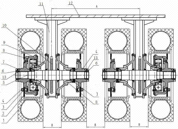
[0013] see figure 1 , the present invention relates to a tire roller suspension system, comprising two groups of suspension devices on the left and right, the tops of the two groups of suspension devices are symmetrically installed on the bottom of the rear floor 12 of the vehicle frame, and the suspension devices include a support box 11, a shaft 5 and Tire 1, the support box 11 is in the shape of a "T", the top of the support box 11 is fixed to the frame rear floor 12, the lower part of the support box 11 is provided with a bearing seat 8, and the shaft 5 passes through the tapered roller bearing 3 is installed on the bearing seat 8.

[0014] The left and right ends of the shaft 5 are all connected to the hub 4 through splines, and the drum brake 9 is installed on the hub 4, and the drum brake 9 is used to control the driving brake of the vehicle. The rim 2 is fixed by bolts, the outer side of the rim 2 is connected with the tire 1, a positioning ring 13 is provided between...


PUM


Abstract

The invention provides a suspension system of a pneumatic tire roller. The suspension system of the pneumatic tire roller is characterized by comprising a left set of suspension device and a right set of suspension device. The tops of the two sets of suspension devices are in bilateral symmetry and arranged on the bottom of a frame back base plate. The suspension device comprises supporting box bodies, shafts and tires. The supporting box bodies are T-shaped. The tops of the supporting box bodies are fixed with the frame back base plate. Bearing seats are arranged on the lower portions of the supporting box bodies. The shafts are arranged on the bearing seats through tapered roller bearings. Chain wheels are arranged inside the supporting box bodies and connected with the shafts. Both the left ends and the right ends of the shafts are connected with hubs through splines. Rims are further fixed on the hubs through bolts. The outer sides of the hubs are connected with the tires. With adoption of the suspension system of the pneumatic tire roller, ground connection specific pressure of the pneumatic tire roller can be improved, compaction capability is improved, component number is reduced, manufacture cost is lowered, and the width of the complete machine is reduced, and transportation is convenient.

Description

technical field [0001] The invention relates to a tire roller suspension system, which belongs to the technical field of engineering machinery. Background technique [0002] Tire rollers are mainly used for road construction, municipal engineering, road maintenance, and ideal compaction equipment for industrial construction sites. However, the traditional tire roller driven by the rear axle has a large overall width, which is inconvenient to transport, and the ground specific pressure of a single tire is small, and the compaction ability of the roller is not high at the same time. Contents of the invention [0003] The object of the present invention is to overcome the above disadvantages and provide a tire roller suspension system with a large ground specific pressure, high compaction capacity, small machine width and convenient transportation. [0004] The purpose of the present invention is achieved like this: [0005] The tire roller suspension system of the present ...

Claims


Application Information

Patent Timeline
Patent Type & Authority Applications(China)
IPC IPC(8): B60G5/00
Inventor 赵小峰郭启华姚凯
Owner 柳工无锡路面机械有限公司
Why Eureka
Try Eureka