
Pin shaft loading and unloading machine

A loader and pin technology, which is applied in metal processing, metal processing equipment, manufacturing tools, etc., can solve the problems of knocking and deformation of the pin head, laborious disassembly and assembly, labor and time consuming, etc., and achieves high assembly precision and efficiency. , mobile and flexible effects

Inactive Publication Date: 2013-06-19
扬州易承重工机械有限公司
View PDF0 Cites 2 Cited by
  • Summary
  • Abstract
  • Description
  • Claims
  • Application Information

AI Technical Summary

Problems solved by technology

[0002] The traditional manual installation needs to be struck with a sledgehammer, which generally requires two people to work together. The direction of the sledgehammer and the center of the pin shaft tend to form a certain angle, and the head of the pin shaft is knocked out (big head), and then As for the need to be reprocessed before use, it is labor-intensive and time-consuming
The disassembly and assembly of the puller is laborious and inefficient

Method used


Image

  • Pin shaft loading and unloading machine
  • Pin shaft loading and unloading machine
  • Pin shaft loading and unloading machine

Examples


Embodiment Construction

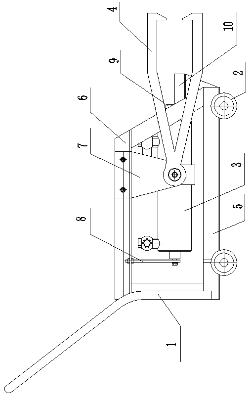
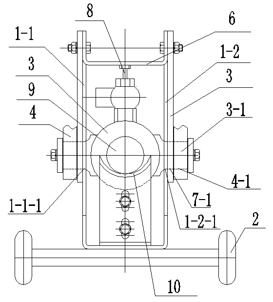
[0009] Such as figure 1 , 2 , 3, the present invention includes a frame 1, a roller 2 arranged around the bottom of the frame 1, a hinged hydraulic cylinder 3, two groups of tension rods 4; the bottom of the frame 1 above the roller 2 is provided with a random accessory platform 5 , the pin shaft placement platform 6 is set on the top of the frame 1; the hinged hydraulic cylinder 3 is arranged between the random accessory platform 5 and the pin shaft placement platform 6, on the left side wall 1-1 of the frame 1, and the right side wall 1- Shaft holes 1-1-1, 1-2-1 are respectively set on 2, and the twisted shafts 3-1 on both sides of the hinge type hydraulic cylinder 3 are respectively inserted in the corresponding shaft holes 1-1-1, 1-2- 1 inside; the outer sides of the left side wall 1-1 and the right side wall 1-2 of the frame 1 are respectively connected to the hanger 7 by nuts, and the first through holes corresponding to the twisted shaft 3-1 are respectively set at...


PUM


Abstract

The invention provides a pin shaft loading and unloading machine and relates to the field of the mechanical manufacturing technology of the pin shaft loading and unloading machine. The pin shaft loading and unloading machine comprises a rack, idler wheels, a hinged-shaft type hydraulic cylinder and two groups of tension bars. Shaft holes are respectively formed in the left sidewall and the right sidewall of the rack. Hinged shafts on two sides of the hinged-shaft type hydraulic cylinder are respectively arranged in the corresponding shaft holes in a penetrating mode. The outer side of the left sidewall of the rack and the outer side of the right sidewall of the rack are respectively connected with a hanging rack through nuts. First through holes corresponding to the hinged shafts are respectively arranged in the lower ends of the hanging rack. Second through holes are respectively formed in the tail ends of the two groups of tension bars. The hinged shafts are respectively arranged in the first through holes and the second through holes in a penetrating mode in sequence. The two groups of tension bars are respectively fastened with the corresponding hanging racks through nuts. An angle regulation stem is arranged at the tail end of the hinged-shaft type hydraulic cylinder. A free end of the angle regulation stem is connected with a pin shaft placing platform through a nut. A cylindrical bearing body is arranged at the front end of a piston rod of the hinged-shaft type hydraulic cylinder. A pin shaft guide groove is arranged in a free end of the cylindrical bearing body. The pin shaft loading and unloading machine is small in size, light in weight, flexible in movement, convenient to use, high in efficiency, timesaving and laborsaving.

Description

technical field [0001] The invention relates to the technical field of manufacturing pin shaft loading and unloading machines. Background technique [0002] The traditional manual installation needs to be struck with a sledgehammer, which generally requires two people to work together. The direction of the sledgehammer and the center of the pin shaft tend to form a certain angle, and the head of the pin shaft is knocked out (big head), and then As for the ability to use after reprocessing, it is labor-intensive and time-consuming. The disassembly and assembly of the puller is laborious and inefficient. Contents of the invention [0003] The purpose of the present invention is to provide a pin loading and unloading machine with small size, light weight, flexible movement, quick and convenient use, high efficiency, time saving and labor saving, no damage to the pin shaft, high assembly precision and high reuse rate for the above ischemia. [0004] The invention comprises a...

Claims


Application Information

Patent Timeline
Patent Type & Authority Applications(China)
IPC IPC(8): B23P19/027
Inventor 董道直刘军
Owner 扬州易承重工机械有限公司
Learn More