
Non-contact type unmanned vehicle driving state measuring system and measuring method

A technology of unmanned vehicles and driving status, which is applied in the direction of radio wave measurement system, registration/indication of vehicle operation, satellite radio beacon positioning system, etc. Limited and other issues to achieve the effect of convenient follow-up viewing

Active Publication Date: 2013-06-12
BIT INTELLIGENT VEHICLE TECH CO LTD
View PDF7 Cites 36 Cited by
  • Summary
  • Abstract
  • Description
  • Claims
  • Application Information

AI Technical Summary

Problems solved by technology

The problem with this method is that it cannot watch the corresponding curve in real time during the operation of the unmanned vehicle
The problem with this method is that the range of the laser radar is limited. For example, a certain 60,000 yuan laser radar has an effective range of only about 45 meters.
For low-reflectivity materials, such as black vehicles, the effective range is lower, and only a range of 20-30 meters can be guaranteed.

Method used


Image

  • Non-contact type unmanned vehicle driving state measuring system and measuring method
  • Non-contact type unmanned vehicle driving state measuring system and measuring method
  • Non-contact type unmanned vehicle driving state measuring system and measuring method

Examples


Embodiment Construction

[0062] In the following description, numerous specific details are given in order to provide a more thorough understanding of the present invention. It will be apparent, however, to one skilled in the art that the present invention may be practiced without one or more of these details. In other examples, some technical features known in the art are not described in order to avoid confusion with the present invention. Embodiments of the present invention will be described below in conjunction with the accompanying drawings.

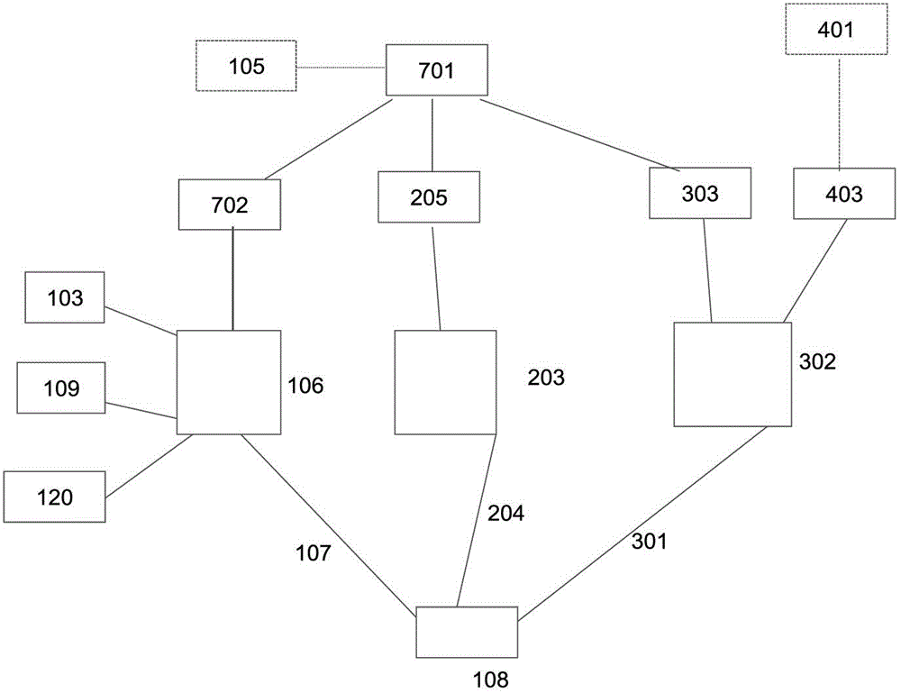
[0063] Such as Figure 1-Figure 3 As shown, the unmanned vehicle driving state measurement system proposed in the present invention includes an unmanned vehicle 8 and a power amplifier type remote electronic tag 111 arranged at the rear of the unmanned vehicle 8, and the manned driver of the unmanned vehicle 8 Vehicle 101, unmanned vehicle driving state measuring device 1, video image recording device 2, comprehensive information display device 3, wirele...


PUM


Abstract

The invention discloses non-contact type unmanned vehicle driving state measuring system and measuring method. The system comprises an unmanned vehicle, a power amplifier type remote distance electronic tag, a manned vehicle, a millimeter-wave radar, a heading sensor, a GPS (Global Positioning System) receiver, a camera, a power amplifier type remote distance electronic tag card reader, an unmanned vehicle driving state measuring device, a video image record device, a comprehensive information display device, a wireless image transmission device, and a terminal receiving and displaying device, wherein the power amplifier type remote distance electronic tag is arranged at the rear part of the unmanned vehicle, the manned vehicle is arranged on the unmanned vehicle, the millimeter-wave radar, the heading sensor, the GPS receiver, the camera, the power amplifier type remote distance electronic tag card reader, the unmanned vehicle driving state measuring device, the video image record device, the comprehensive information display device and the wireless image transmission device are arranged on the manned vehicle, and the terminal receiving and displaying device is positioned remotely. With the method, the driving state parameters, such as trace and speed, of the unmanned vehicle can be obtained by real-time measurement through a non-contact mode, the speed curve and trace curve of the unmanned vehicle can be drawn in real time.

Description

technical field [0001] The invention relates to the technical field of measurement systems for driving state of unmanned vehicles, in particular to a non-contact measurement system and method for driving state of unmanned vehicles. Background technique [0002] The monitoring of the intelligent behavior of unmanned vehicles in complex environments and the measurement of their driving state parameters (such as speed and driving position) are the scientific evaluation of the research level of key technologies such as environment perception and behavior decision-making of unmanned vehicles. prerequisites. [0003] In order to ensure that the monitoring measurement is accurate, effective, reliable and practical, it is necessary to design a driving state monitoring and measurement system for unmanned vehicles to realize accurate monitoring and measurement of unmanned vehicles. [0004] Unmanned vehicles are generally equipped with GPS, inertial navigation system, odometer, etc.,...

Claims


Application Information

Patent Timeline
IPC IPC(8): G07C5/08G01S19/42G01S17/50
Inventor 熊光明龚建伟刘鹏李勇陈慧岩
Owner BIT INTELLIGENT VEHICLE TECH CO LTD
Learn More