Video-recording switching component of microscope

A technology of adapter components and microscopes, which is applied in the direction of microscopes, optical components, optics, etc., can solve the problems of inconvenient transmission of pictures immediately, the inability to have one physician in charge, expensive equipment, etc., and achieve real-time collection and digitization Upscaling and management, rich photo layers, and fast capture effects

Active Publication Date: 2013-06-12
肖扬
View PDF7 Cites 4 Cited by
  • Summary
  • Abstract
  • Description
  • Claims
  • Application Information

AI Technical Summary

Problems solved by technology

[0004] 1. It is necessary to use a beam splitter and a camera interface, both of which contain lens components and have a complex structure;
[0005] 2. The light reflection of the shooting target obtained by the camera from the beam splitter accounts for 20 to 50% of the incident light of the eyepiece. It is necessary to use a special flash unit to enhance the reflection of the shooting target to improve the imaging quality, but the intensity of light stimulation to the patient is high;
[0006] 3. It is necessary to use a SLR camera or an industrial control camera, and also need to configure a professional image acquisition card;
[0007] 4. It is not convenient to transfer pictures immediately;
[0008] 5. The equipment is expensive and not easy to popularize. It is impossible to have one attending physician, and it is impossible to shoot immediately in the consultation room environment, which requires the assistance of technical personnel.

Method used


Image

  • Video-recording switching component of microscope
  • Video-recording switching component of microscope
  • Video-recording switching component of microscope

Examples


Embodiment Construction

[0039] In order to better explain the present invention and facilitate understanding, the microscope camera-video adapter assembly of the present invention will be further described in detail through specific embodiments in conjunction with the accompanying drawings.

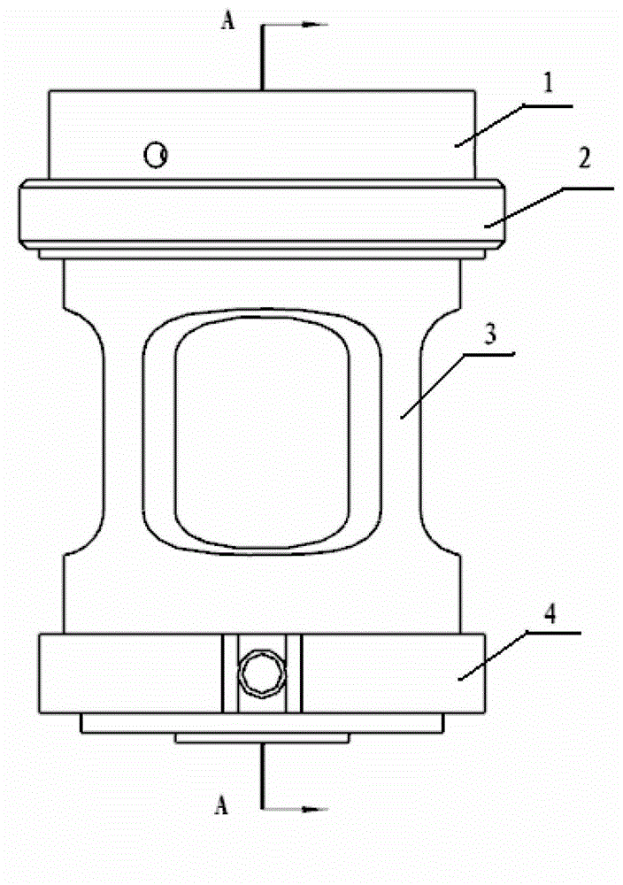
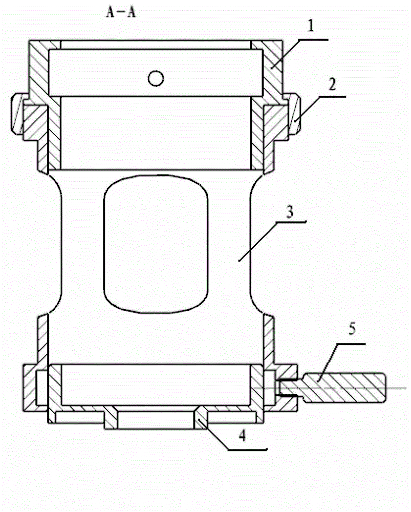
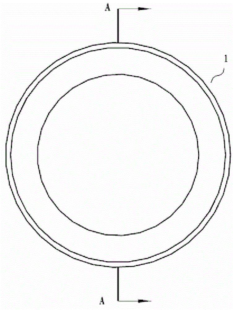
[0040] see Figure 1A to Figure 5B , the microscope camera video adapter assembly of the present invention comprises: a limit ring 1, a bridging ring A3 and a bridging ring B4, the three are connected in sequence, preferably concentrically arranged, and form an optical path in the center, so that After connecting the eyepiece of the microscope to the camera of the video recording device through the adapter assembly, ensure that the optical axis of the microscope coincides with the optical axis of the video recording device, so that the image in the eyepiece of the microscope can be clearly captured by the camera.

[0041] The microscope is an optical microscope, including a slit lamp microscope.

[0042] The ca...


PUM


Abstract

The invention relates to a video-recording switching component of a microscope. The video-recording switching component comprises a spacing ring, a bridging ring A and a bridging ring B which are arranged concentrically and are connected in sequence, wherein one end of the spacing ring is sleeved and fastened on the periphery of the root of an eyepiece inserting slot of the microscope, and the other end of the spacing ring is sleeved with an inner side end A of the bridging ring A; an eyepiece of the microscope is placed into the bridging ring A through the inner side end A of the bridging ring A; an outer side end A of the bridging ring A and an inner side end B of the bridging ring B are sleeved together and can rotate relative to each other; an outer side end B of the bridging ring B is provided with a hollow stud capable of being connected with video recording equipment or a video recording equipment fixing device; and after the hollow stud is connected with the video recording equipment or the video recording equipment fixing device, an opening of the hollow stud is over against a camera of the video recording equipment and forms an optical positioning relationship with the camera, so that the camera can conveniently record images in the eyepiece. The switching component disclosed by the invention adopts an afocal light path design, does not contain any lens component, totally obtains light reflection of a shot target from the eyepiece, and has the advantages of simple structure, low cost and clear imaging.

Description

technical field [0001] The invention relates to a photographic adapter device, in particular to an adapter assembly that can use videography equipment for microscope videography. Background technique [0002] With the increasing demand for patient follow-up, health education, telemedicine, peer communication and medical risk prevention, the collection of ophthalmic imaging data is becoming more and more important, especially the clinical value of high-quality ophthalmic imaging data is very important. Slit lamp photomicrographs are the most basic, intuitive and irreplaceable image data in ophthalmology. Obtaining high-quality ophthalmic imaging data usually requires high-quality special camera equipment, and its cost is often too high. For small-scale ophthalmology units, generally only equipped with popular slit lamp microscopes, it is difficult to obtain high-quality ophthalmic imaging data. Simultaneously, for the consideration of computer system security, common specia...

Claims


Application Information

Patent Timeline
Patent Type & Authority Applications(China)
IPC IPC(8): G02B21/36
Inventor 肖扬高敏郝燕生郭继虎潘雪马剑欣王育红窦键昇
Owner 肖扬
Why Eureka
Try Eureka