
Electronic load module of power supply aging test and power supply aging test system

An electronic load, power aging technology, applied in power testing, parts of electrical measuring instruments, measuring electricity, etc., can solve the problems of inconvenient product quality analysis and evaluation, few optional specifications, large resistance error, etc. The mode and parameter settings are flexible and fast, convenient for system maintenance, and the effect of saving labor costs

Inactive Publication Date: 2013-06-12
SHENZHEN ZHONGKEYUAN ELECTRONICS
View PDF4 Cites 35 Cited by
  • Summary
  • Abstract
  • Description
  • Claims
  • Application Information

AI Technical Summary

Problems solved by technology

[0004] ① The resistance value of the resistor is fixed, and there are few optional specifications, many of which need to be customized from the factory;
[0005] ② The power supply specifications are various, and the resistance cannot be accurately matched to the accurate current required for aging;
[0006] ③ The resistance error is large, and it is easy to produce deviation after temperature rise, which cannot ensure 100% load aging of the product;
[0007] ④ Adjusting the load size needs to be calculated first, and the selection of load resistance can only obtain an approximate current value;
[0008] ⑤ The aging process cannot be automatically monitored, and manual inspections are required one by one, which is inefficient and easy to miss;
[0009] ⑥ It is impossible to record the parameters of the aging process, which is not convenient for quality traceability management;
[0010] ⑦ The aging report cannot be generated, which is not convenient for the analysis and evaluation of product quality;
The second-generation load overcomes the first three shortcomings of the first-generation load, but the latter four shortcomings are still prominent and cannot meet the needs of modern production processes
Although there are many standard test electronic load instruments on the market that can fully meet the aging requirements in terms of performance and functions, such instruments are usually expensive, bulky, and are mainly designed for R&D, engineering, production and other testing purposes, which is difficult to achieve. System networking with hundreds of channels for mass aging

Method used


Image

  • Electronic load module of power supply aging test and power supply aging test system
  • Electronic load module of power supply aging test and power supply aging test system
  • Electronic load module of power supply aging test and power supply aging test system

Examples


Embodiment 1

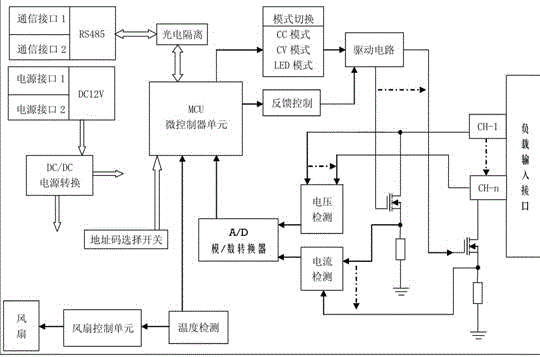
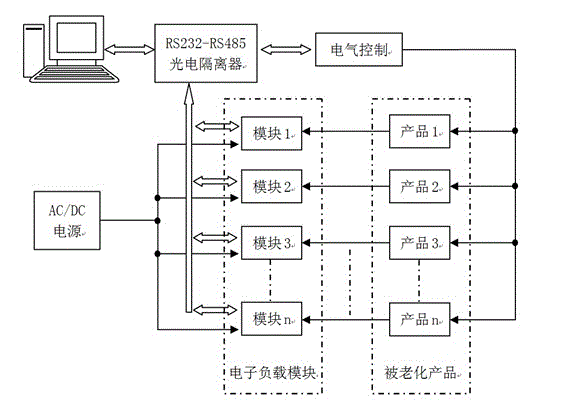
[0047] Example 1, such as figure 1 , figure 2 As shown, this embodiment is a power aging test system such as a power aging room or an aging car composed of a group of electronic load modules for power aging testing and a host computer, such as figure 2 As shown: the system can perform aging tests on several aging power supplies at the same time, and the host computer controls and monitors them uniformly, displays and records the test process, and realizes the automation and intelligence of power supply aging tests. The technical solution of the power supply aging test system is: the The power supply aging test system includes a group of electronic load modules for power supply aging test. The electronic load modules for each power supply aging test perform aging tests on the tested power supply respectively, and also includes a host computer. The host computer communicates with each The electronic load modules of the power aging test are connected to each other, receive the...


PUM


Abstract

The invention provides an electronic load module of a power supply aging test and a power supply aging test system. The electronic load module of the power supply aging test provides an intelligent electronic load module controlled by an MCU (Microprogrammed Control Unit). According to the power supply aging test system, a plurality of electronic load modules of the power supply aging test are uniformly managed, displayed and stored by adopting an upper computer, so that the system is the intelligent power supply aging test system.

Description

technical field [0001] The invention relates to the field of electronic loads in power supply aging test equipment, in particular to a programmable electronic load module used for switching power supply aging tests and aging test systems such as aging vehicles and aging rooms composed of many such electronic load modules. Background technique [0002] In order to test and improve the reliability, stability and safety of power supply products, the aging test of power supply products has become an important link in the production process of such products. The so-called "burn-in" refers to a long-term full-load test (also called burn-in test or burn-in, English name: Burn-in Test) of power supply products under a harsh high-temperature condition to simulate possible occurrences in actual use. harsh conditions to test the performance of the product. [0003] The dummy load used in traditional burn-in test equipment is mostly high-power resistors, which is the first generation o...

Claims


Application Information

Patent Timeline
IPC IPC(8): G01R1/00G01R31/40
Inventor 吴涛庞成黄明雄
Owner SHENZHEN ZHONGKEYUAN ELECTRONICS
Learn More