
Feeding device of stone sawing machine

A technology of feeding device and stone sawing machine, which is applied in the direction of stone processing tools, stone processing equipment, work accessories, etc., can solve the problems of increasing the conveying load of the stone sawing machine, increasing the processing steps of sawing stone, and the high scrap rate of stone processing. Ideal processing effect, strong humanized design, simple and reasonable structure

Active Publication Date: 2013-06-12
广东威德力机械实业股份有限公司 +1
View PDF9 Cites 1 Cited by
  • Summary
  • Abstract
  • Description
  • Claims
  • Application Information

AI Technical Summary

Problems solved by technology

The conveyor belt of the invention transports the stones forward, and the stone pushing mechanism pushes the stones forward on the back side of the stones, preventing the conveyor belt from slipping when the stone sawing machine transports large stones, and increasing the conveying capacity of the stone sawing machine. load, which is convenient for processing larger or heavier stones; however, the surface of the conveyor belt is a plane, and each time the stone pusher pushes the stone to the saw blade for processing, the processing size of the stone can only be measured by additional tools , increasing the processing procedure of sawing stones, the work efficiency is low, and the measurement error is large, the accuracy is low, and the processing scrap rate of stones is high

Method used


Image

  • Feeding device of stone sawing machine
  • Feeding device of stone sawing machine
  • Feeding device of stone sawing machine

Examples


Embodiment Construction

[0019] The present invention will be further described below in conjunction with the accompanying drawings and embodiments.

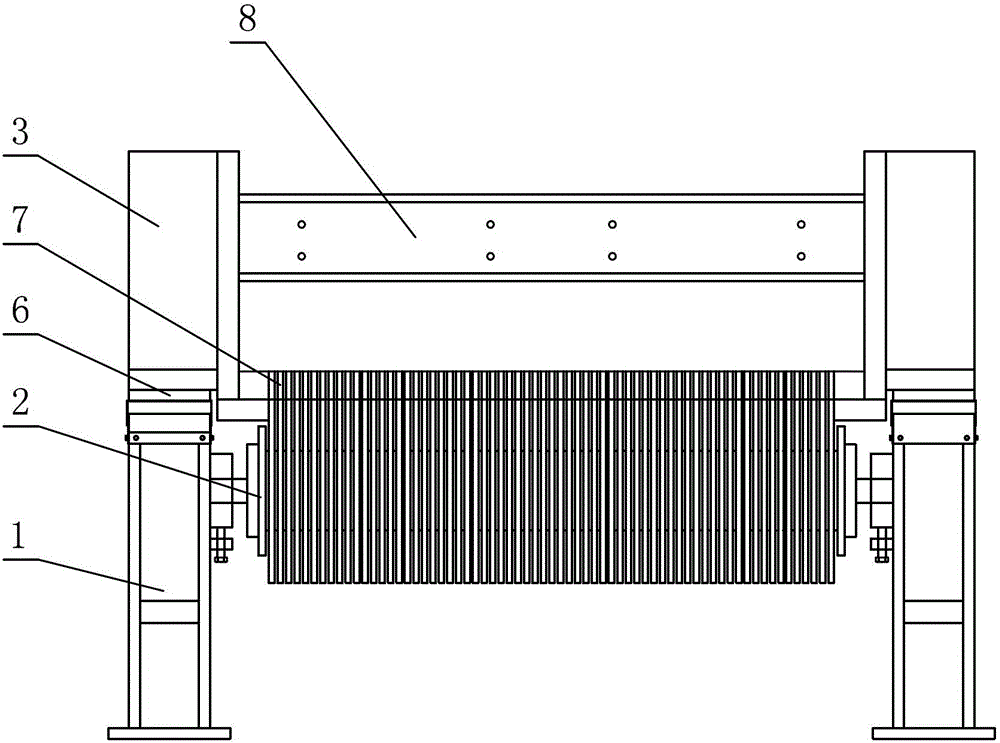
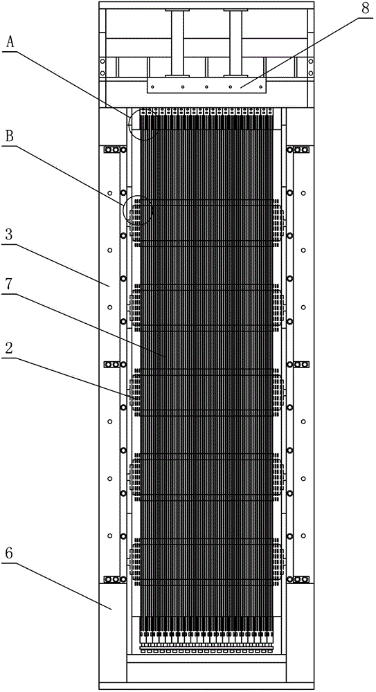
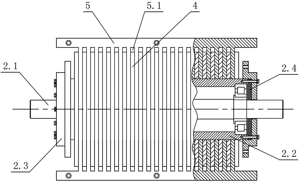
[0020] see Figure 1-Figure 5 , the feeding device of the stone sawing machine includes a left-right symmetrically arranged workbench base 1, a feed roller 2 connected between the workbench bases 1, and a guide rail (not shown in the figure) above the workbench base 1. can be marked) and the vertical plate 3 of the stone pressing frame, the bottom of the vertical plate 3 of the stone pressing frame is provided with a slider fixing plate 6, and the slider fixing plate 6 is provided with a slider corresponding to the guide rail (not marked in the figure), the vertical plate of the stone pressing frame 3 is slidably arranged on the guide rail through the slider fixing plate 6, and a number of rollers 4 are uniformly arranged on the feeding roller 2, and gap grooves 4.1 are arranged between adjacent rollers 4.

[0021] The feeding roller 2 includes a rolle...


PUM


Abstract

The invention discloses a feeding device of a stone sawing machine, which comprises a workbench base arranged symmetrically right and left, and a feeding drum connected in the middle of the workbench base, wherein a guide rail and a stone pressure rack stand plate are arranged above the workbench base; the stone pressure rack stand plate is slidingly arranged on the guide rail; the feeding device is characterized in that a plurality of rolling wheels are uniformly arranged on the feeding drum; and a gap groove is formed between every two adjacent rolling wheels. According to the feeding device, the rolling wheels are arranged on the feeding drum of the stone sawing machine, the gap groove is formed between every two adjacent rolling wheels, the feeding workbench and saw blades are connected with the gap grooves in a matching manner respectively, stone blocks to be processed are fixed on the feeding workbench, and the feeding workbench makes rectilinear movement under guiding of the feeding drum and the gap grooves, so that the stone blocks can make rectilinear motion and be in a smooth placement state all the time; cutting and processing of the saw blades are facilitated; the processing rejection rate of the processed stone blocks is low; the smoothness of the processed stone blocks is high; and the rolling wheels on the feeding drum can adjust a gap distance according to a cutting demand of a user.

Description

technical field [0001] The invention relates to a stone sawing machine, in particular to a feeding device of the stone sawing machine. Background technique [0002] On March 28, 2012, I disclosed a feeding structure of a stone sawing machine in Chinese Patent Document No. CN102390095A. It includes conveying platforms arranged on the front and rear sides of the sawing stone gantry, and the conveying platform is provided with synchronously conveying stones. The conveyor belt and conveyor chain of the block are also provided with a push stone mechanism on the conveyor chain. The conveyor chain is arranged parallel to the left and right sides of the conveyor belt through the conveyor chain drive shafts arranged at the front and rear ends of the conveyor table, and the stone pushing mechanism is horizontally placed on the conveyor chain; the stone pushing mechanism includes clamping blocks symmetrically arranged on the two conveyor chains The left and right clamping blocks are d...

Claims


Application Information

Patent Timeline
Patent Type & Authority Applications(China)
IPC IPC(8): B28D7/00B28D1/02
Inventor 周金生
Owner 广东威德力机械实业股份有限公司
Learn More