Angle adjusting and clamping method for milling jig

A milling machine fixture and angle adjustment technology, which is applied in the direction of clamping, positioning devices, manufacturing tools, etc., can solve the problems of class A fixtures that are not universal, poor angle locking, waste of materials, etc., to save time for inclination angle adjustment and yield Improvement and good self-locking effect

Active Publication Date: 2015-03-11
钱汝玉
View PDF6 Cites 0 Cited by
  • Summary
  • Abstract
  • Description
  • Claims
  • Application Information

AI Technical Summary

Problems solved by technology

[0007] However, Type A fixtures are not universal—wasting materials; the parallelism of Type A, B, C, and D fixtures relative to the X and Z axes of the machine tool needs to be adjusted with a dial indicator every time the machine is installed—wasting time; A , B, C, and D fixtures use screws to cooperate with the pressure plate to press the workpiece-wasting time; A, B, C, and D fixtures have no standard reference benchmark when setting the tool-wasting time; D fixtures do not adjust the angle. Fine adjustment - waste of time; Poor angle locking of class D fixtures - poor security

Method used


Image

  • Angle adjusting and clamping method for milling jig
  • Angle adjusting and clamping method for milling jig
  • Angle adjusting and clamping method for milling jig

Examples


Embodiment Construction

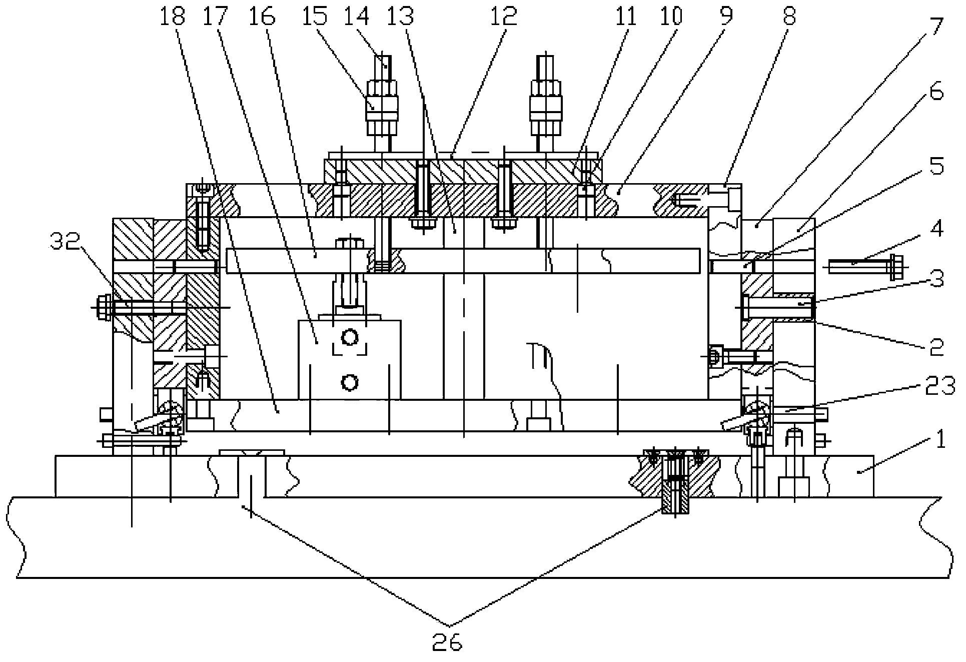
[0034] Figure 1 to Figure 4 The specific structure of the universal jig for fast positioning pneumatic pressing and fine adjustment of inclination angle is shown. It includes a bracket installed on the workbench 28, and a box body is rotatably connected to the bracket. The box body includes two side plates 8 parallel to each other, and the bottoms of the two side plates are vertically fixed to the base of the cylinder. On the seat plate 18, a top plate 9 is vertically fixed on the top of the two side plates, and the top plate 9 is the positioning panel of the flat fixture 11.

[0035] A flat clamp 11 is fixed on the top plate 9 , and the flat clamp 11 is used for installing a workpiece 12 . The flat fixture 11 is provided with workpiece positioning pins 31 for positioning the workpiece 12 . The flat clamp 11 is positioned on the top plate 9 of the box body through the stepped pin 10, and the flat clamp 11 and the top plate of the box body are fixed by bolts.

[0036] The u...


PUM


Abstract

The invention discloses an angle adjusting and clamping method for a milling jig. The clamping method for a workpiece on the milling jig comprises the steps that a flat fixture is fixed on a top plate of a box and positioned on the top plate of the box by stepped pins; the flat fixture is fixed with the top plate of the box by bolts; the workpiece is arranged on the flat fixture; the workpiece is positioned by workpiece locating pins arranged on the flat fixture; piston rods of the cylinders move downwards to drive a pressure plate frame, pressure plate bolts and pressure plates to move downward to ensure that the pressure plates allow the workpiece to be compressed on the flat fixture; and angle adjustment of the box on the milling jig comprises a gear fine adjustment and an indexing mechanism fine adjustment. With the adoption of the method, when middle and small parts are cut, the workpiece can be quickly positioned and compressed, and a fixture inclination can be adjusted.

Description

technical field [0001] The invention relates to a universal clamp for milling machines. Background technique [0002] Milling machine fixtures in the prior art usually adopt the following four schemes: [0003] A. For different angle requirements, use wire cutting to make simple fixtures with fixed angles; [0004] B. A fixed universal fixture parallel to the plane formed by the X and Y axes of the machine tool; [0005] C. A fixed universal fixture parallel to the plane formed by the X and Z axes of the machine tool; [0006] D. A simple general-purpose angle fixture is formed by combining sheets. [0007] However, Type A fixtures are not universal—wasting materials; the parallelism of Type A, B, C, and D fixtures relative to the X and Z axes of the machine tool needs to be adjusted with a dial indicator every time the machine is installed—wasting time; A , B, C, and D fixtures use screws to cooperate with the pressure plate to press the workpiece-wasting time; A, B, C,...

Claims


Application Information

Patent Timeline
Patent Type & Authority Patents(China)
IPC IPC(8): B23Q3/04B23Q3/08B23Q1/26B23Q16/08
Inventor 钱汝玉
Owner 钱汝玉
Why Eureka
Try Eureka