
Electromagnetic vector sensor array amplitude and phase error self-correcting method based on array rotation

A sensor array, electromagnetic vector technology, applied in the direction of measuring electrical variables, instruments, measuring devices, etc., can solve the problems of difficult to accurately control the arrival direction of the signal, poor achievability, etc.

Inactive Publication Date: 2013-06-05
XIDIAN UNIV
View PDF5 Cites 22 Cited by
  • Summary
  • Abstract
  • Description
  • Claims
  • Application Information

AI Technical Summary

Problems solved by technology

In terms of electromagnetic vector antenna error correction, K.T. Wong first proposed a mathematical model of the in-situ error, and estimated the in-situ error using three correction sources with known directions of arrival; then Huang Jiacai and Zhang Ruige further improved K.T. Wong’s in-situ error Error estimation algorithm; Zou Jingjing et al. studied the magnitude and phase errors among multiple electromagnetic vector sensors under the assumption that a single electromagnetic vector sensor is an ideal model; Liao Guisheng et al. Phase error, the amplitude and phase error correction method is to use the same correction source to transmit two signals with the same arrival direction and known signal to correct the error, but in practical applications, the arrival direction of the signal is often difficult to control accurately, and it can be realized poor sex

Method used


Image

  • Electromagnetic vector sensor array amplitude and phase error self-correcting method based on array rotation
  • Electromagnetic vector sensor array amplitude and phase error self-correcting method based on array rotation
  • Electromagnetic vector sensor array amplitude and phase error self-correcting method based on array rotation

Examples


Embodiment Construction

[0032] In order to make the above and other objects, features and advantages of the present invention more apparent, the following specifically cites the embodiments of the present invention, together with the attached drawings, for a detailed description as follows.

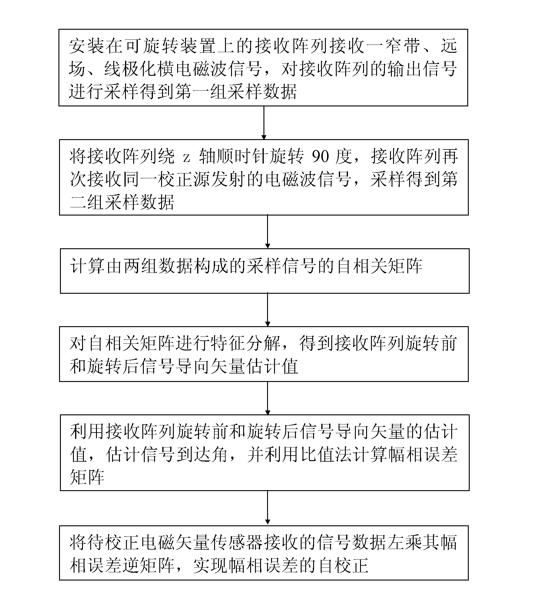
[0033] refer to figure 1 as shown, figure 1It is a flowchart of the present invention. In the method of the present invention, the receiving array is composed of L electromagnetic vector sensors, and is installed on a rotatable device. Assuming that the electromagnetic vector sensors only have amplitude and phase errors, a narrow-band, far-field, linearly polarized transverse electromagnetic wave is used to correct the source signal pair The electromagnetic vector sensor array self-corrects the amplitude and phase errors, and the arrival angle of the transverse electromagnetic wave correction source signal is Angle of polarization is (γ, η), and the specific implementation steps of the inventive method are as...


PUM


Abstract

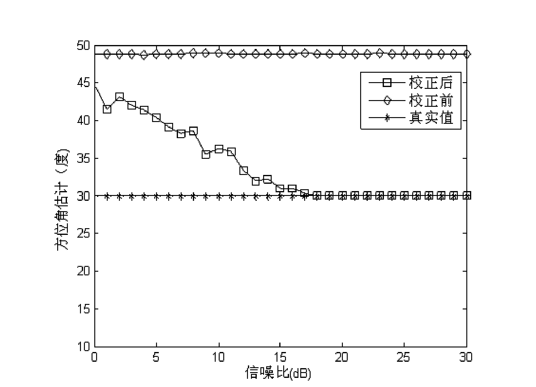
The invention discloses an electromagnetic vector sensor array amplitude and phase error self-correcting method based on array rotation. The method includes: an electromagnetic vector sensor with amplitude and phase errors is used as a receiving array and installed on a rotation device to receive a transverse electromagnetic wave calibration source signal, two groups of sampling data of an array output signal are received before the array rotates and after the array rotates 90 degrees around a z axis in clockwise mode, a sampling signal autocorrelation matrix formed by the two groups of sampling data is calculated, characteristic decomposition is performed on the sampling signal autocorrelation matrix to obtain signal guiding vector estimation values before and after rotation of an array and estimate an amplitude and phase error matrix, and an array element to be corrected receives an inverse matrix of a data premultiplication amplitude and phase error matrix so as to achieve correction of amplitude and phase errors. The electromagnetic vector sensor array amplitude and phase error self-correcting method based on the array rotation can estimate amplitude errors and signal arrival angles of the signal of the electromagnetic vector sensor, has high parameter estimation accuracy, does not need iterative operation, and is small in calculated amount.

Description

technical field [0001] The invention belongs to the technical field of electromagnetic vector sensor error correction, in particular to a self-correction method for the amplitude and phase error of an electromagnetic vector sensor array. Background technique [0002] Electromagnetic vector sensors can obtain the polarization information of electromagnetic signals. The development and utilization of electromagnetic wave polarization information can effectively improve the capabilities of radar systems in anti-jamming, target recognition, detection, and tracking. Compared with the scalar antenna sensor array, the electromagnetic vector sensor array has the following advantages: small geometric size, high resolution capability, wideband signal processing, no spatial undersampling problem, and no time synchronization problem. These superior properties make polarization-sensitive arrays have important application value and broad application prospects in military and civil affairs...

Claims


Application Information

Patent Timeline
IPC IPC(8): G01R35/00
Inventor 王兰美史耀媛王桂宝
Owner XIDIAN UNIV
Learn More