High temperature photoelectric sensor

A photoelectric sensor and high-temperature technology, applied in the direction of electric radiation detectors, etc., can solve the problems that the measurement accuracy cannot meet the requirements, the application limit of photoelectric thermometers, and the upper limit of temperature measurement cannot be exceeded, etc., so that it is easy to form an industrial automatic control system and use And the effect of low maintenance cost and simple structure

Inactive Publication Date: 2013-06-05
FEMTO TECH XIAN
View PDF0 Cites 2 Cited by
  • Summary
  • Abstract
  • Description
  • Claims
  • Application Information

AI Technical Summary

Problems solved by technology

When thermocouples are used at high temperatures, their lifespan is short, the cost is high, and they are greatly restricted by the use environment, and the upper limit of temperature measurement cannot exceed 2300°C; photoelectric thermometers have achieved significant development and progress in recent years, but the measurement accuracy cannot reach The required situation has not been fundamentally improved, so the application of photoelectric thermometers is also subject to certain restrictions.
Especially in industrial high-temperature measurement, the sensor only perceives part of red light and infrared light, and the spectral width is also limited

Method used


Image

  • High temperature photoelectric sensor

Examples


Embodiment Construction

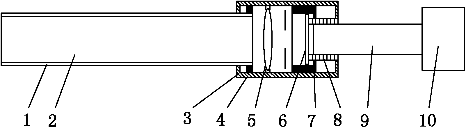
[0025] like figure 1 As shown, the present invention includes a high-temperature conductor composed of a high-temperature cavity tube 1 and a high-temperature conduction tube 2, a metal casing 4 with both left and right side walls open, fixed in the metal casing 4 and concentrating and concentrating the light source to be measured. The optical lens group 5 for guiding light, the filter 6 arranged in parallel on the right side of the optical lens group 5 and performing spectrum selection on the light emitted by the light source to be measured, the optical fiber 9 fixed on the opening on the right side of the metal shell 4, and The right end of the optical fiber 9 is connected to the photoelectric conversion device 10 and the fastening device 7 arranged in the metal casing 4 . The left end of the high-temperature conduction tube is connected to the light source to be measured, and the right end of the high-temperature conduction tube passes through the left opening of the metal ...


PUM


Abstract

The invention discloses a high temperature photoelectric sensor. The high temperature photoelectric sensor comprises a high temperature conduction machine formed by a high temperature cavity pipe and a high temperature conduction pipe, a metal shell with both open left and right lateral walls, an optical lens group used for condensation and conduction of a to-be-measured light source, an optical filter plate used for selecting frequency spectrums to light rays emitted by the to-be-measured light source, an optical fiber, a photovoltaic conversion device and a clamping device, wherein the left end of the optical fiber is fixed on an opening on the right side of the metal shell through a fixing support, the photovoltaic conversion device is connected with the right end of the optical fiber, and the clamping device is used for clamping the fixing support. The high temperature conduction pipe is arranged inside the high temperature cavity pipe in a sleeved mode, the left end of the high temperature conduction pipe is connected with the to-be-measured light source, the right end of the high temperature pipe penetrates through an opening on the left side of the metal shell and is over against the optical lens group, and the left end of the optical fiber is over against the filter plate. The high temperature photoelectric sensor has the advantages of being rational in structure and design, convenient to process and manufacture, simple and convenient to use and operate, good in use effect, high reaction speed, strong in antijamming capability, high in measuring accuracy, long in service life, and the like. The high temperature photoelectric sensor facilitates to form an industrial automatic control system.

Description

technical field [0001] The invention relates to a photoelectric conversion device, in particular to a high temperature photoelectric sensor. Background technique [0002] With the advent of the new technology revolution, the world has begun to enter the information age. In the process of using information, the first problem to be solved is to obtain accurate and reliable information, and sensors are the main way and means to obtain information in the fields of nature and production. [0003] At present, the sensors used for higher temperature measurement in the industrial production process mainly include thermocouples and photoelectric series thermometers. When the thermocouple is used at high temperature, the life is short, the cost is high, and it is greatly restricted by the use environment, and the upper limit of temperature measurement cannot exceed 2300 °C; photoelectric thermometers have made significant development and progress in recent years, but the measurement a...

Claims


Application Information

Patent Timeline
Patent Type & Authority Applications(China)
IPC IPC(8): G01J5/10
Inventor 麻树波
Owner FEMTO TECH XIAN
Why Eureka
Try Eureka