
Truss for lifting power transmission line tower connecting leg and erection method

A transmission line tower and truss technology, which is applied in the field of truss and transmission line tower raising, which can solve the problem of the distance between the original transmission line tower to the ground, the insufficient distance limit, the difficulty of determining the erection position due to the shortage of land resources, natural conditions and terrain conditions Complex and changeable problems, to achieve the effect of convenient erection and operation, simple and reasonable structure, and simple and reasonable design structure

Active Publication Date: 2013-06-05
STATE GRID CORP OF CHINA +1
View PDF4 Cites 11 Cited by
  • Summary
  • Abstract
  • Description
  • Claims
  • Application Information

AI Technical Summary

Problems solved by technology

[0002] At present, due to the gradual increase in the height of buildings, roads, and railways in urbanization construction in many areas, the distance to the ground and the limited distance of the original transmission line tower are not enough, so it needs to be raised
However, the size and span of transmission line towers must meet certain requirements. Necessary minimum safety distances should be maintained between buildings, ground, roads and other overhead lines, and between conductors and lightning conductors. For transmission line towers, it is very difficult to determine the location where land resources are tight. If new transmission line towers are replaced at the original location, due to the large number of transmission line towers, wide distribution, complex and changeable natural conditions and terrain conditions, it is not conducive to the use of large-scale transmission line towers. Equipment transportation and erection are time-consuming and labor-intensive, increasing costs

Method used


Image

  • Truss for lifting power transmission line tower connecting leg and erection method
  • Truss for lifting power transmission line tower connecting leg and erection method
  • Truss for lifting power transmission line tower connecting leg and erection method

Examples


Embodiment 1

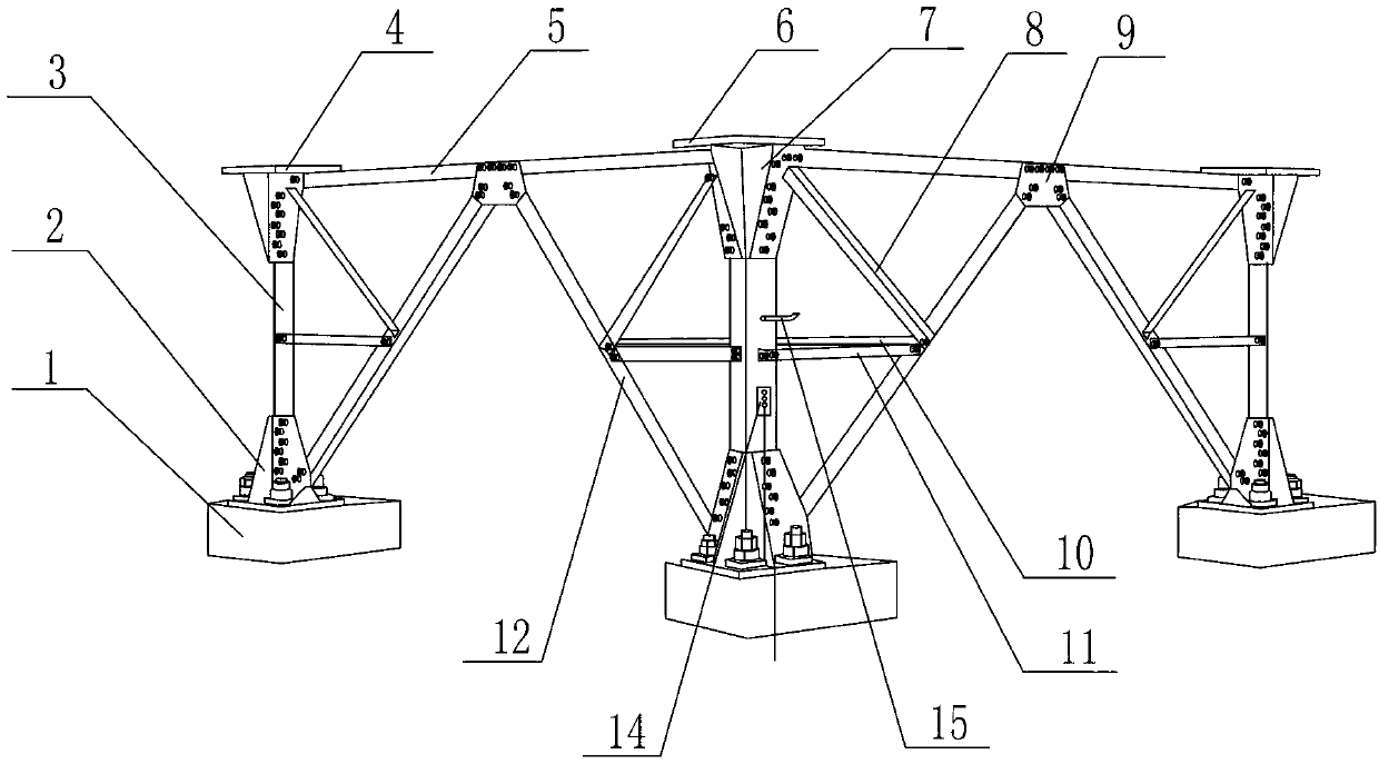
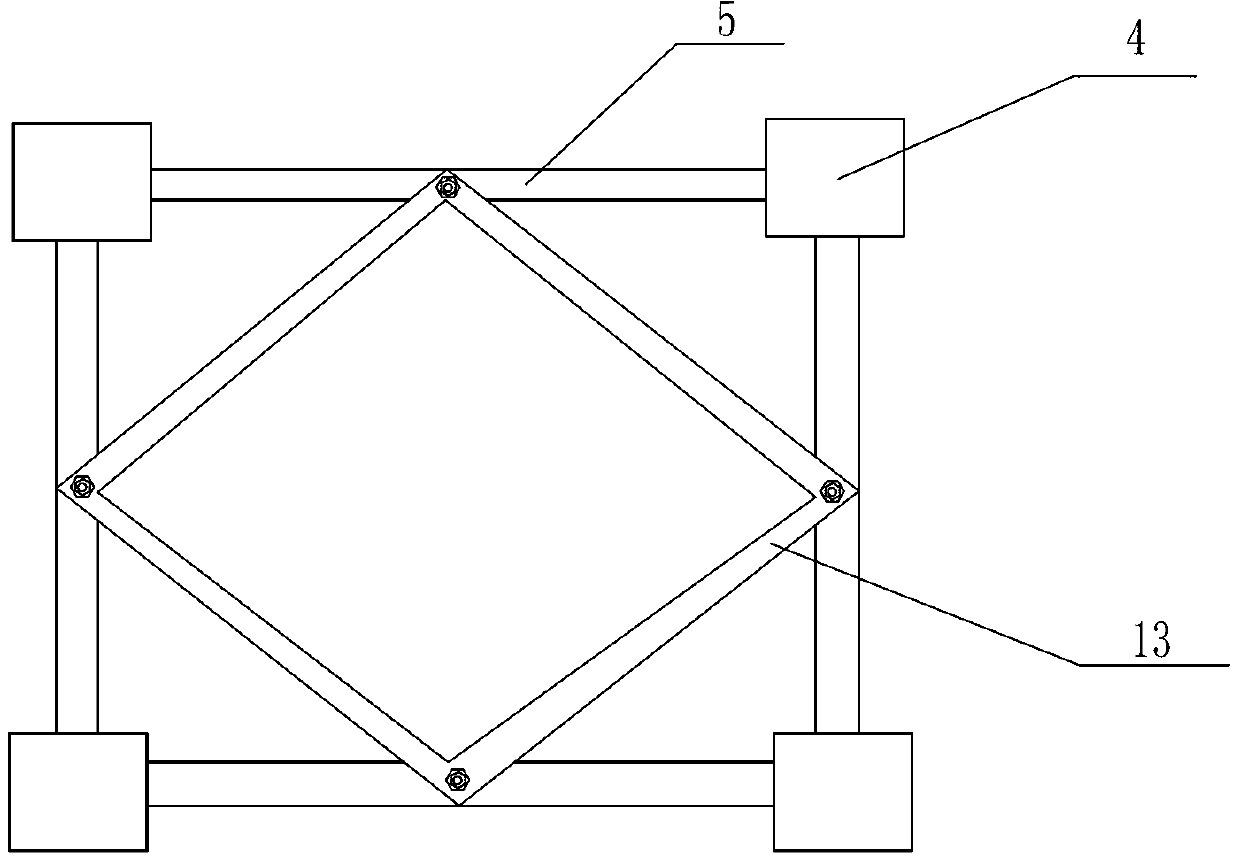
[0040] like figure 1 As shown, the truss used to raise the tower leg of the transmission line includes the installation foundation platform 1, and is characterized in that it also includes four support beams 5, and the four support beams 5 are connected end to end to form a square structure, and two adjacent supports A support base 4 is installed at the intersection of the cross members 5, and the main material angle steel 3 is installed at the lower end of the support base 4, and the fixed base 2 is installed at the lower end of the main material angle steel 3, and the fixed base 2 is installed on the installation base 1.

[0041] The support base 4 includes a base steel plate 6 and two vertically staggered fixed stiffened steel plates 7, the fixed stiffened steel plate 7 is arranged vertically to the base steel plate 6, and ○-shaped round holes are arranged on the two fixed stiffened steel plates 7;

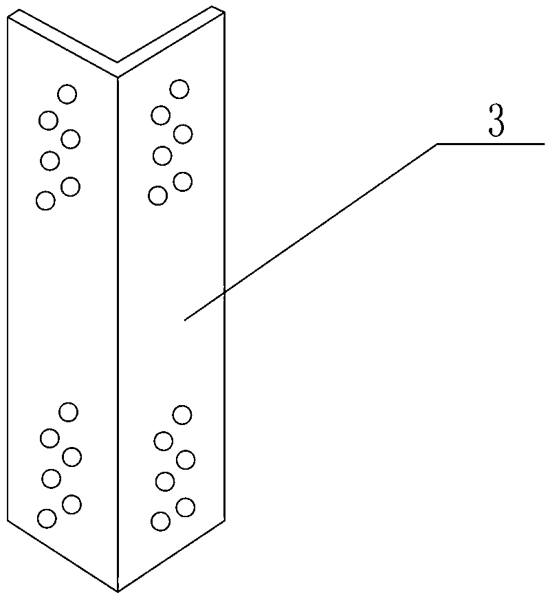
[0042] The two sides of the main material angle steel 3 form an angle of 9...

Embodiment 2

[0047] like figure 1 , figure 2 , image 3 As shown, on the basis of Embodiment 1, the four supporting beams 5 are all provided with connecting plates 9 at the middle positions, and the connecting plates 9 are connected to one end of the first reinforced angle steel oblique material 12, and the other end of the first reinforced angle steel oblique material 12 One end is connected to the fixed base 2.

Embodiment 3

[0049] like figure 1 , figure 2 , image 3 As shown, on the basis of Embodiment 1 and Embodiment 2, the middle of the first reinforcement angle steel oblique material 12 is set to connect one end of the second reinforcement angle steel oblique material 11 and the third reinforcement angle steel oblique material 8, and the second reinforcement angle The other end of the angle steel oblique material 11 is connected to the middle position of the main material angle steel 3 , and the other end of the third reinforcement angle steel oblique material 8 is connected to the support base 4 .

[0050] The middle positions of the two first reinforcement angle steel slant materials 12 adjacent to both sides of the main material angle steel 3 are fixedly connected by the fourth reinforcement angle steel slant material 10 .

[0051] The middle positions of every two adjacent support beams 5 of the four support beams 5 are fixedly connected by the fifth reinforcement angle steel oblique m...


PUM


Abstract

The invention relates to a truss, in particular to a truss for lifting a power transmission line tower connecting leg and an erection method, and belongs to the field of electric power system devices. The truss comprises an installation base table, and is characterized by further comprising four supporting transverse materials, the four supporting transverse materials are connected into a square structure in a head-to-tail manner, a supporting base is installed at the intersection point of each two adjacent supporting transverse materials, main material angle steel is installed at the lower end of each supporting base, and a fixing base is installed at the lower end of the main material angle steel and installed on the installation base table. The problem of distance limitation in operation of an original power transmission line in-channel tower is solved, safety operation of a line is ensured, the pile position of the original power transmission line tower is lifted and heightened, land acquisition, path change, additional cost adding and production of a new power transmission line tower are omitted, the truss is convenient, time-saving and labor-saving in erection and can realize safety operation, the erection method is simply and reliably implemented, and the truss is low in erection difficulty, fine in flexibility and high in practicability.

Description

technical field [0001] The invention relates to a truss, in particular to a truss and an erection method for raising transmission line tower legs, belonging to the field of power system devices, and mainly used for raising power transmission line towers. Background technique [0002] At present, due to the gradual increase in the height of buildings, roads, and railways in urbanization construction in many areas, the distance to the ground and the limit distance of the original transmission line tower are not enough, and they need to be raised. However, the size and span of transmission line towers must meet certain requirements. Necessary minimum safety distances should be maintained between buildings, ground, roads and other overhead lines, and between conductors and lightning conductors. For transmission line towers, it is very difficult to determine the location where land resources are tight. If new transmission line towers are replaced at the original location, due to ...

Claims


Application Information

Patent Timeline
IPC IPC(8): E04H12/18E04H12/22
Inventor 赵延华杨春雷张伟杨学杰于景岳李龙远李宋林冯曰敏王世涛袁振宗崔学涛
Owner STATE GRID CORP OF CHINA
Learn More