


Quick Research
Generate reliable direction feasibility study reports for your R&D in just a few steps.

Technical Q&A
Discover and master advanced knowledge NOW. Basics, ideas, possibilities, all at once.

Find Solutions
As an expert in R&D theories, this can generate solutions to your technical problems instantly.

Evaluate Feasibility
Analyze your overall solution with one click, know your potential R&D risks in advance.

Monitor Landscape
Get weekly tech updates, stay abreast of the latest tech innovations and key insights.
Discharge door structure of double-horizontal-shaft forced-type bituminous mixture blender
A technology of asphalt mixture and double-horizontal shafts, which is applied in the direction of the unloading device, can solve the problems of large mixing dead angle, poor sealing, and difficult wear gap, etc., and achieve the advantages of reduced mixing dead angle, wide sealing surface and reliable sealing performance Effect
- Summary
- Abstract
- Description
- Claims
- Application Information
AI Technical Summary
Problems solved by technology
Method used
Image

Examples
Embodiment 1
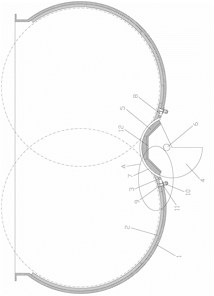
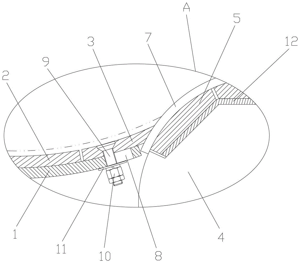
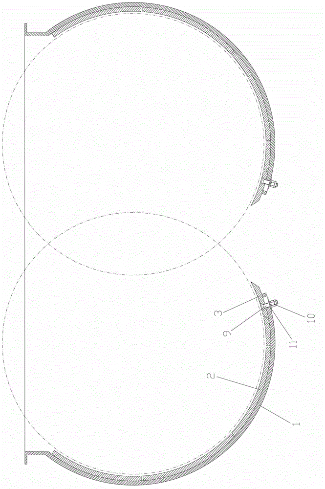
[0047] like Figure 1 to Figure 9 As shown, a discharge door structure of a twin-shaft forced asphalt mixer, including a pot body liner 2 and a pot side liner 3 fixed on the inner side of the twin-shaft forced asphalt mixer pot shell 1, fixed on the The shaft end seal 7 on the end side wall of the twin-shaft forced asphalt mixture mixer and the rotary unloader arranged at the discharge port at the bottom of the twin-shaft forced asphalt mixer and matched with the shaft end seal 7 The material door, the lower part of the pot shell 1 of the twin-shaft forced asphalt mixer and the first waist hole 8 is opened near the discharge port, the side liner 3 of the pot is long and the double-shaft forced asphalt mixing Mixer pot shell 1, the pot side liner 3 is fixed on the twin-shaft forced asphalt mixer pot shell 1 by the first bolt 9 and can adjust the position along the first waist hole 8, the rotary discharge The door includes a material door main body, a material door liner 5 and ...
Embodiment 2
[0055] like Figure 10 to Figure 14 As shown, the difference between this embodiment and Embodiment 1 is that the number of the material door liner 5 arranged radially along the material door liner connecting plate 12 is one, and the shape of the material door liner 5 is arc-shaped. The outer surface of the material door liner connecting plate 12 is an arc surface, and the radius of the outer surface of the material door liner connecting plate 12 is equal to the radius of the inner surface of the material door liner 5 to achieve seamless fit; the shaft end The sealing member 7 is an end face seal ring, and a third waist hole 16 is opened on the end face seal ring, and the end face seal ring is fixed on the side of the twin-shaft forced asphalt mixer through the third bolt 13 and the third gasket 17. On the side wall of the end and can adjust the position along the third waist hole 16, the end face of the end face sealing ring and the end face of the material gate end plate 4 a...
Embodiment 3
[0057] like Figure 15 and Figure 16 As shown, the difference between this embodiment and Embodiment 1 is that: the shaft end seal 7 is a shaft end sealing plate, the second waist hole 7-1 is opened on the shaft end sealing plate, and the shaft end sealing plate It is fixed on the end side wall of the twin-shaft forced asphalt mixer through the second bolt 7-2 and the second gasket 7-3 and can adjust the position along the second waist hole 7-1, and the shaft end is sealed The seal plate cooperates with the material door lining plate 5 to realize the axial sealing of the discharge door, and the end surface of the shaft end sealing plate protrudes from the end surface of the material door lining plate 5 . During specific use, the installation position of the shaft end seal 7 can be adjusted according to the actual situation, and then the sealing gap between the shaft end seal 7 and the material door liner 5 can be adjusted, so that the shaft end seal 7 and the material door l...
PUM
 Abstract
Description
Claims
Application Information
 - R&D Engineer
- R&D Manager
- IP Professional
- Industry Leading Data Capabilities
- Powerful AI technology
- Patent DNA Extraction
Browse by: Latest US Patents, China's latest patents, Technical Efficacy Thesaurus, Application Domain, Technology Topic, Popular Technical Reports.
© 2024 PatSnap. All rights reserved.Legal|Privacy policy|Modern Slavery Act Transparency Statement|Sitemap|About US| Contact US: help@patsnap.com