
Solar backlight source and light-emitting banner

A technology of backlight and solar energy, which is applied in the field of lighting, can solve the problems of high cost input, high power consumption, and good lighting effects, and achieve low output power requirements, low power consumption, and good lighting effects

Inactive Publication Date: 2013-05-29
ZHEJIANG MINGSHUO ENERGY SAVING TECH
View PDF7 Cites 4 Cited by
  • Summary
  • Abstract
  • Description
  • Claims
  • Application Information

AI Technical Summary

Problems solved by technology

[0004] Based on this, it is necessary to use more point light sources for traditional backlight sources, more complex circuits, higher cost input, higher power consumption, and uneven light distribution. To solve the problem of achieving a better lighting effect, it provides a method that uses less point light sources, has simpler circuits, lower cost, less power consumption, more uniform light distribution, and does not affect the lighting effect after local point light sources are damaged. Solar Backlight

Method used


Image

  • Solar backlight source and light-emitting banner
  • Solar backlight source and light-emitting banner
  • Solar backlight source and light-emitting banner

Examples


Embodiment Construction

[0021] The present invention will be described in detail below in conjunction with the accompanying drawings and specific embodiments.

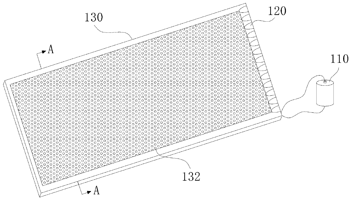
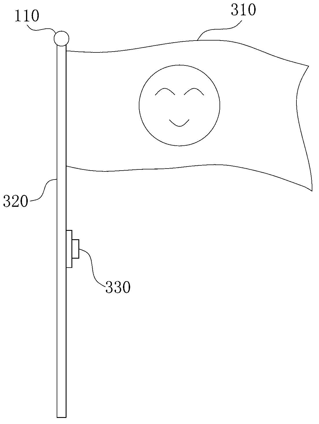
[0022] Such as figure 1 and figure 2 As shown, in one embodiment, a solar backlight includes a solar cell 110 , a plurality of LED light sources 120 and a light guide plate 130 . A plurality of LED light sources 120 are respectively connected in parallel to the voltage output terminals of the solar cell 110. Usually, the solar cell 110 is charged with green light energy and automatically stores electric energy to provide power for the LED light source in a dark environment. Since the energy consumption of the LED light source 120 is small, the charged solar battery 110 can fully meet the energy consumption requirements of multiple LED light sources 120 . In this embodiment, the solar backlight also includes a light-controlled delay switch or a timing switch. The light-controlled delay switch or timing switch is connected in the connection...


PUM


Abstract

A solar backlight source and a light-emitting banner comprise a solar cell, a plurality of light-emitting diode (LED) light sources and light guide plates, wherein the plurality of the LED light sources are respectively connected with a voltage output end of the solar cell in parallel, and the plurality of the LED light sources are arranged on the side surface of the light guide plates. Each light guide plate is provided with two surfaces, wherein at least one surface is provided with a plurality of concave points, the concave points are identical in sizes and in hemispherical shapes or rectangular shapes, and the surface of each concave point is rough. The solar backlight source and the light-emitting banner have the advantages of being little in using point light source, simpler in line, lower in cost, smaller in energy consumption of a light source, and uniform in light distribution. Moreover, the luminous effect can not be influenced after a local point light source is damaged, and marketing is benefited.

Description

technical field [0001] The invention relates to the field of lighting, in particular to a solar backlight source and a luminous flag. Background technique [0002] With the development of lighting technology, backlight sources are used more and more widely. For example, backlights used in national flags, billboards, billboards, etc. A traditional backlight usually arranges a plurality of point light sources evenly on the surface of the flat panel, and uses more point light sources, more complicated connection lines, higher cost, higher power consumption, and the brightness of the backlight near the point light sources is higher. Well, the brightness far away from the point light source is darker, and the light distribution is uneven. Moreover, after the local point light source is damaged, the backlight source is partially dimmed, and a good lighting effect cannot be achieved. Another type of backlight is to arrange multiple point light sources evenly on the side of the li...

Claims


Application Information

Patent Timeline
Patent Type & Authority Applications(China)
IPC IPC(8): F21S9/03F21V8/00F21V23/04G09F17/00G09F13/20F21Y101/02F21Y115/10
Inventor 余海明
Owner ZHEJIANG MINGSHUO ENERGY SAVING TECH
Learn More