Three-dimensional hole shape detection method and system based on optical coherence tomography

A technology of optical coherence tomography and detection method, which is applied in the field of three-dimensional hole shape detection based on optical coherence tomography scanning, and can solve the problems of limited scanning range of optical coherence tomography and inability to scan imaging.

Inactive Publication Date: 2016-01-13
刘茂珍 +2
View PDF5 Cites 2 Cited by
  • Summary
  • Abstract
  • Description
  • Claims
  • Application Information

AI Technical Summary

Problems solved by technology

However, optical coherence tomography cannot perform large-scale scanning imaging due to the limitation of scanning range.

Method used


Image

  • Three-dimensional hole shape detection method and system based on optical coherence tomography
  • Three-dimensional hole shape detection method and system based on optical coherence tomography
  • Three-dimensional hole shape detection method and system based on optical coherence tomography

Examples


Embodiment 1

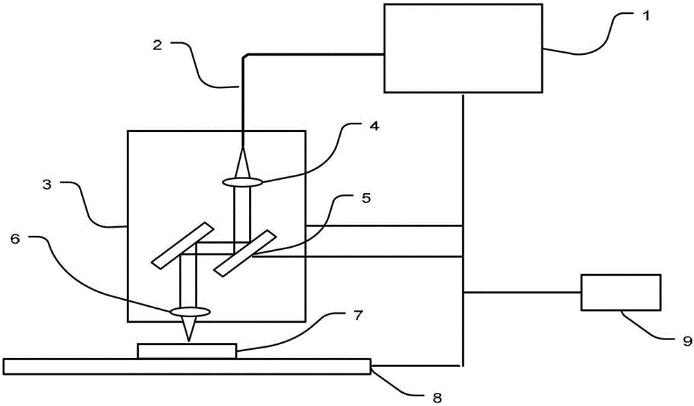
[0026] A three-dimensional hole shape detection system based on optical coherence tomography, such as figure 1 As shown, it is mainly composed of an optical coherence tomography device 1 , a system fiber collimator 4 , a two-dimensional scanning galvanometer 5 , a scanning objective lens 6 , a vertical translation platform 3 , a translation platform 8 and a computer 9 . Both the longitudinal movement platform 3 and the translation platform 8 are connected with the computer 9, and the computer 9 controls the movement of the longitudinal movement platform 3 and the translation platform 8. The system fiber collimator 4 , the two-dimensional scanning galvanometer 5 , and the scanning objective lens 6 are fixed on the longitudinal movement platform 3 and follow the movement of the longitudinal movement platform 3 . The circuit board 7 to be tested is placed on the translation platform 8 and moves along with the translation platform 8 . The longitudinal movement platform 3 is verti...

Embodiment 2

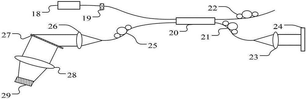
[0046] The system configuration and detection method of embodiment 2 are basically the same as those of embodiment 1, the difference is that in the three-dimensional hole shape detection system based on optical coherence tomography, the optical coherence tomography device 1 used is changed to a spectral domain optical coherence layer Analytical imaging device, see image 3 . At this time, the optical coherence tomography device 1 is mainly composed of a broadband continuous light source 18, an optical isolator 19, a spectral domain fiber coupler 20, 3 polarization controllers 21, 22, 25, 2 fiber collimators 23, 26, Mirror 24, grating 27, spectral objective lens 28 and line scan camera 29 are composed. The broadband continuous light source 18 emits a broadband spectrum, enters the spectrum domain fiber coupler 20 through the optical isolator 19, and is divided into two beams by the spectrum domain fiber coupler 20, one of which passes through the first polarization controller ...


PUM


Abstract

The invention discloses a three-dimensional hole-shape detection method and a detection system based on optical coherence tomography. By means of optical coherence tomography, a three-dimensional structural image of a blind hole or a through hole of a circuit board is obtained directly, the information about the hole especially depth, upper pore diameter, lower pore diameter, residual glue, base copper damage and the like of the blind hole is obtained after the image is processed, and the quality of the blind hole or the through hole is automatically detected and evaluated. The three-dimensional hole-shape detection method and the detection system based on optical coherence tomography have the advantages of being high in measurement accuracy, high in reliability of measured result, low in cost, high in speed, and the like.

Description

technical field [0001] The invention relates to the field of optical coherence tomography-based scanning, in particular to a three-dimensional hole shape detection method and system based on optical coherence tomography. Background technique [0002] At present, for the quality of printed circuit boards, most manufacturers use manual visual inspection, but manual inspection has its own defects, such as low production efficiency and poor stability. In order to overcome the shortcomings of manual visual inspection, people have designed an automatic optical imaging (Auto Optics Imaging, AOI). And analysis, compared with the standard image, to obtain the defects of the measured object, so as to realize the visual inspection of the planar appearance of the circuit board at different stages in the circuit board manufacturing. This method is simple and fast, but it can only detect one plane, and cannot effectively measure the depth of blind holes. In order to obtain more accurate...

Claims


Application Information

Patent Timeline
Patent Type & Authority Patents(China)
IPC IPC(8): G01B11/22G01B11/08G01N21/45
Inventor 刘茂珍李喜锦李育华
Owner 刘茂珍
Why Eureka
Try Eureka