
LED lighting device

An LED lighting, free technology, applied in the field of LED lighting, can solve the problems of difficult LED lighting devices to quickly set up, difficult to carry, etc., to achieve the effect of fast set up, easy to carry, and avoid damage

Inactive Publication Date: 2013-05-22
PR LIGHTING
View PDF9 Cites 2 Cited by
  • Summary
  • Abstract
  • Description
  • Claims
  • Application Information

AI Technical Summary

Problems solved by technology

[0003] However, the size of the LED lighting device with a wide light-emitting surface tends to increase, so its transportation becomes difficult. In addition, even if the above-mentioned LED lighting device is disassembled to make it easy to carry, the LED lighting device needs to be installed. assembly, making quick setup of LED lighting fixtures difficult

Method used


Image

  • LED lighting device
  • LED lighting device
  • LED lighting device

Examples


Embodiment 1

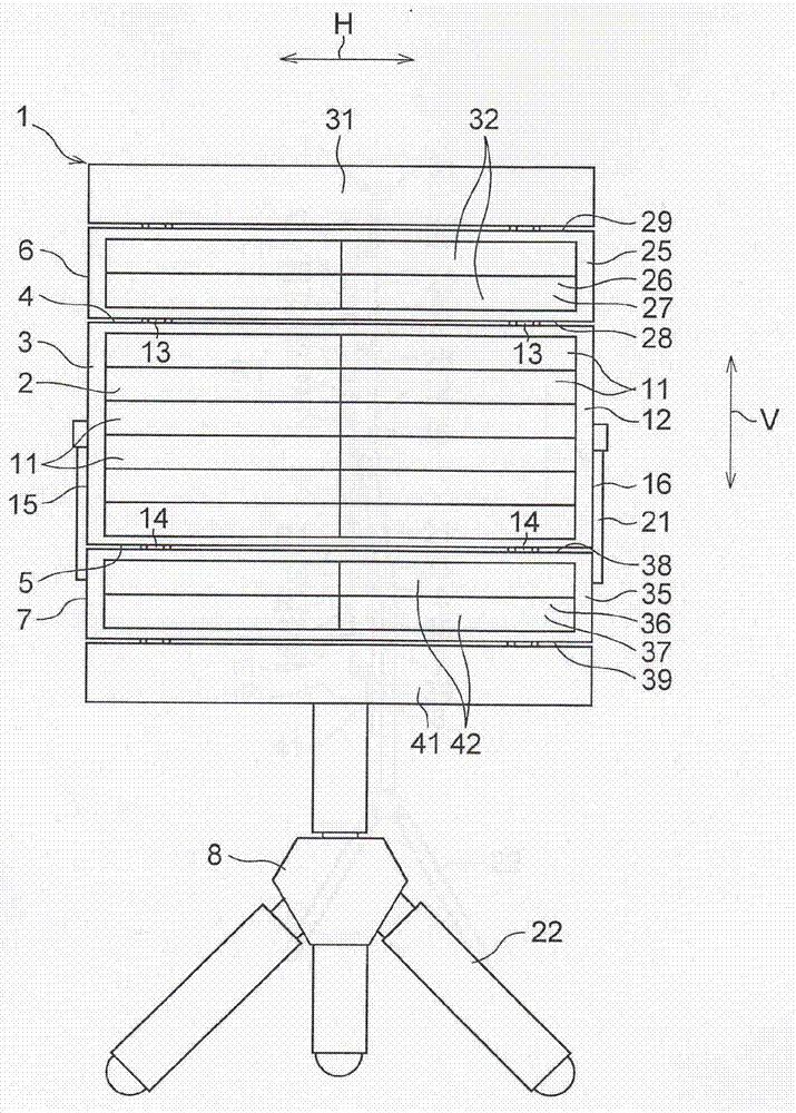
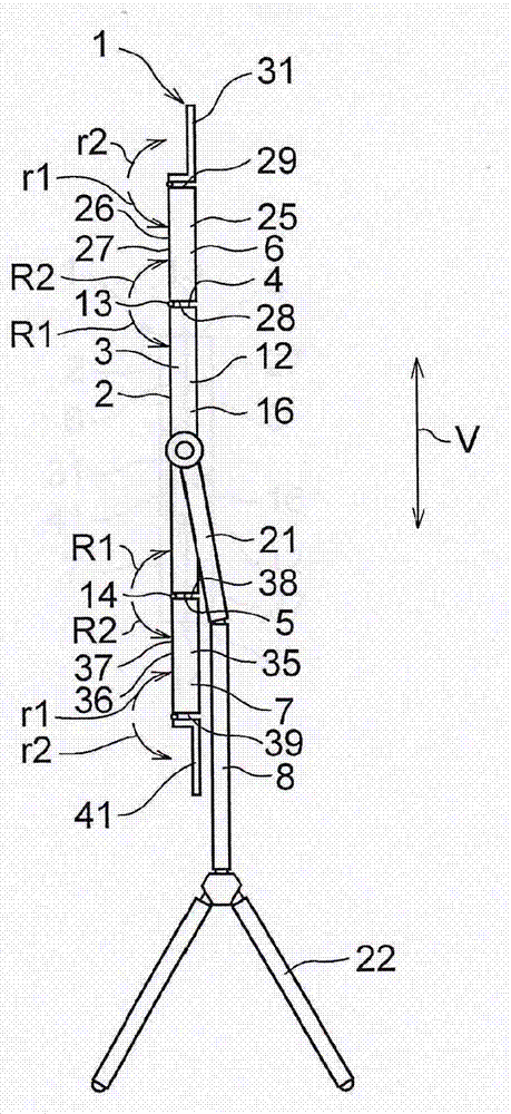
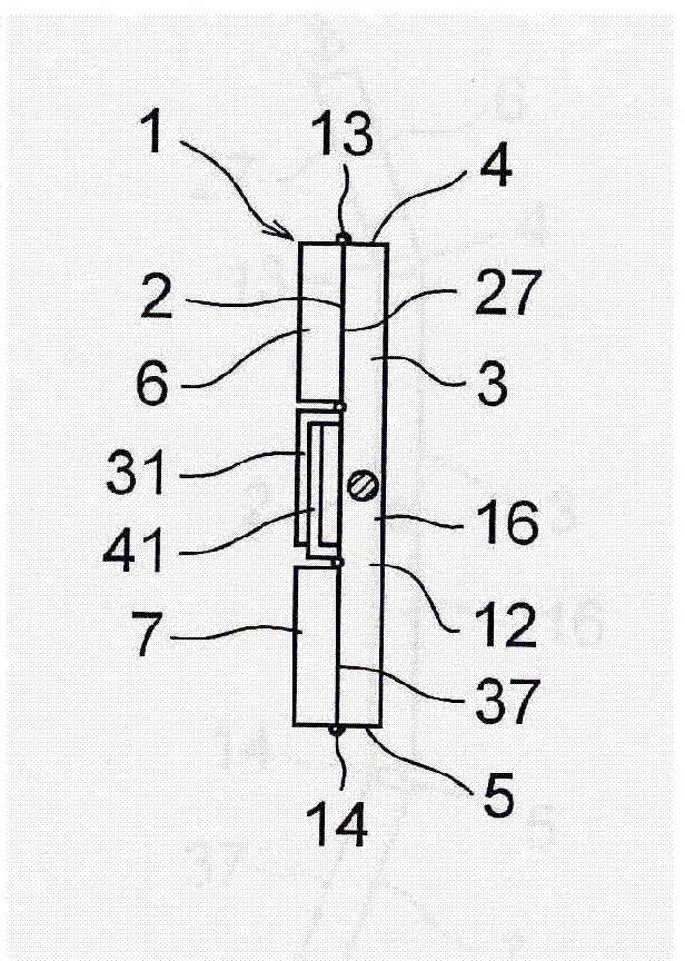
[0033] Such as Figure 1 to Figure 4 As shown, the foldable LED lighting device 1 of the present embodiment includes: a rectangular plate-shaped light-emitting board 3, a pair of free-rotating plates 6 and 7 of the same shape respectively connected to the upper edge 4 and the lower edge 5 of the light-emitting board 3 , and a support body 8, the luminous plate 3 has a luminous surface 2 formed by arranging a plurality of light-emitting diodes (not shown), and the pair of freely rotating plates 6 and 7 can rotate around the axis extending along the horizontal direction H toward The directions R1 and R2 can be rotated freely, and the support body 8 supports the light-emitting panel 3 .

[0034] The light-emitting surface 2 is composed of a plurality of light source boards formed by arranging a plurality of light-emitting diodes, and in this embodiment, it is composed of twelve light source boards 11 that are laterally wider.

[0035] Such as figure 1 As shown, the configuratio...

Embodiment 2

[0061] In the LED lighting device 1 described in this embodiment, it may also include Figure 5 Instead of the freely pivoting panels 6 and 7 , free pivoting panels 46 and 47 constituted by visors are shown. The widths of the freely rotating plates 46 and 47 in the vertical direction V can also be half of the light emitting surface 2 of the light emitting plate 3 .


PUM


Abstract

The invention discloses an LED lighting device which comprises a rectangular and plate-shaped light emitting panel, and a pair of freely rotating plates of the same shape which are respectively connected to an upper edge and a lower edge of the light emitting panel, wherein the light emitting panel comprises a light emitting surface arranged with a plurality of light emitting diodes, and the freely rotating plates can freely rotate around a shaft extending along a horizontal direction. The freely rotating plates, when rotating to a same direction, can overlap the light emitting panel to cover the light emitting surface, and when rotating to the other direction, can unfold to expose the light-emitting surface. According to the invention, a relatively wide light emitting surface can be formed, so as to facilitate carrying and rapid setting up, and the light emitting surface may not be damaged during carrying.

Description

technical field [0001] The invention belongs to the field of LED lighting, and in particular relates to an LED lighting device. Background technique [0002] In Japanese Patent (Japanese Patent Laid-Open No. 2007-258114), a lighting device is disclosed, which includes: LED (also known as: Light Emitting Diode, Light Emitting Diode) mounting body, a plurality of LED mounting bodies installed on the LED elements, and lens elements respectively mounted on these plurality of LED elements. [0003] However, the size of the LED lighting device with a wide light-emitting surface tends to increase, so its transportation becomes difficult. In addition, even if the above-mentioned LED lighting device is disassembled to make it easy to carry, the LED lighting device needs to be installed. Assembling is performed, so quick setup of the LED lighting device is difficult. In addition, the LED lighting device may be impacted by being dropped or the like during transportation, however, it ...

Claims


Application Information

Patent Timeline
Patent Type & Authority Applications(China)
IPC IPC(8): F21S6/00F21V14/08F21V14/02F21Y101/02
CPCF21L2/00F21V1/10F21Y2105/001F21V21/30F21Y2105/10F21Y2115/10
Inventor 木村三郎池田喜明梁志远
Owner PR LIGHTING
Learn More