Electroplating workpiece conveying mechanism

A technology for conveying mechanisms and workpieces, applied in electrolytic components, electrolytic processes, etc., to improve efficiency and solve electroplating problems

Inactive Publication Date: 2016-02-10
PLASTIC ENG
View PDF9 Cites 0 Cited by
  • Summary
  • Abstract
  • Description
  • Claims
  • Application Information

AI Technical Summary

Problems solved by technology

[0003] The purpose of the present invention is to provide a conveying mechanism for electroplating workpieces in view of the deficiencies in the prior art, which can not only solve the problem of electroplating ultra-high parts, but also improve production efficiency

Method used


Image

  • Electroplating workpiece conveying mechanism
  • Electroplating workpiece conveying mechanism
  • Electroplating workpiece conveying mechanism

Examples


Embodiment Construction

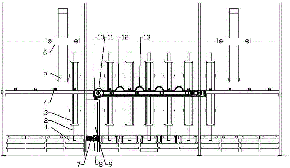
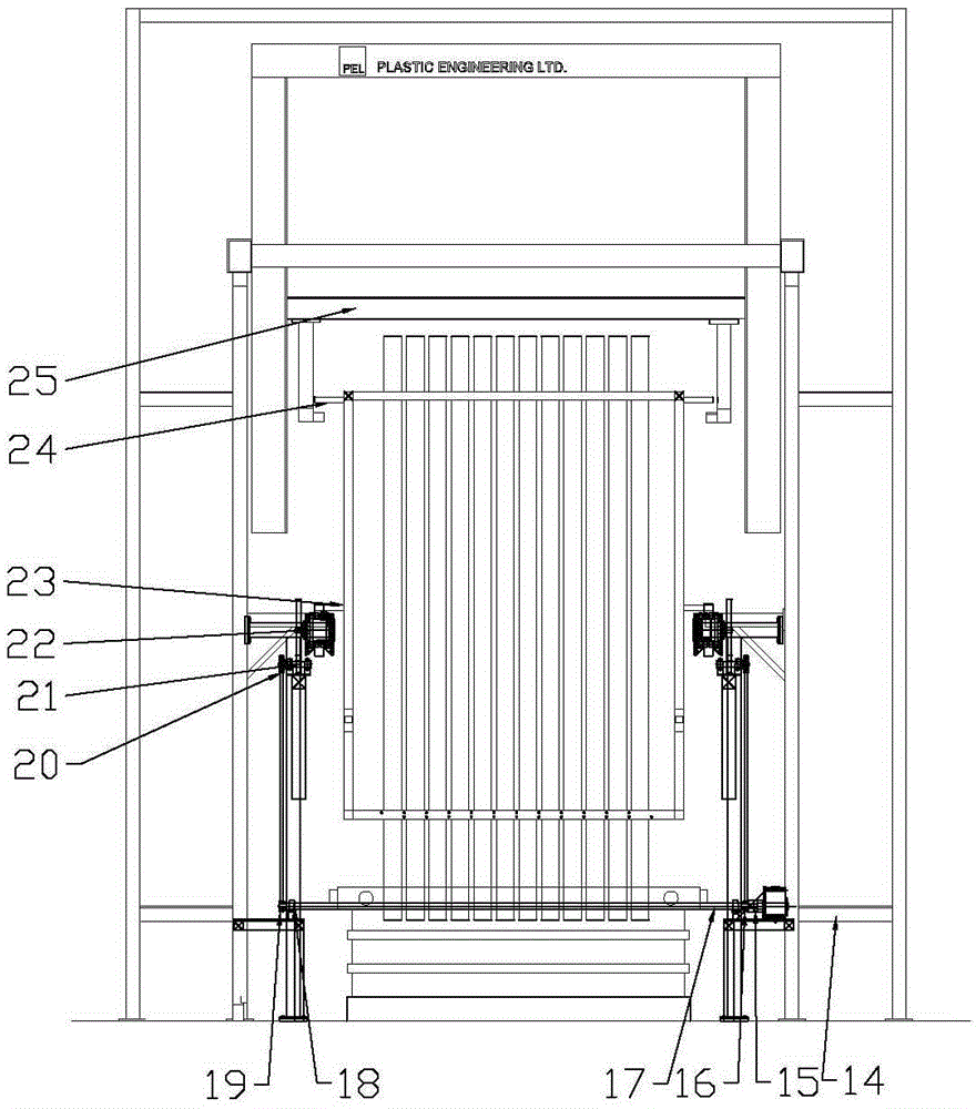
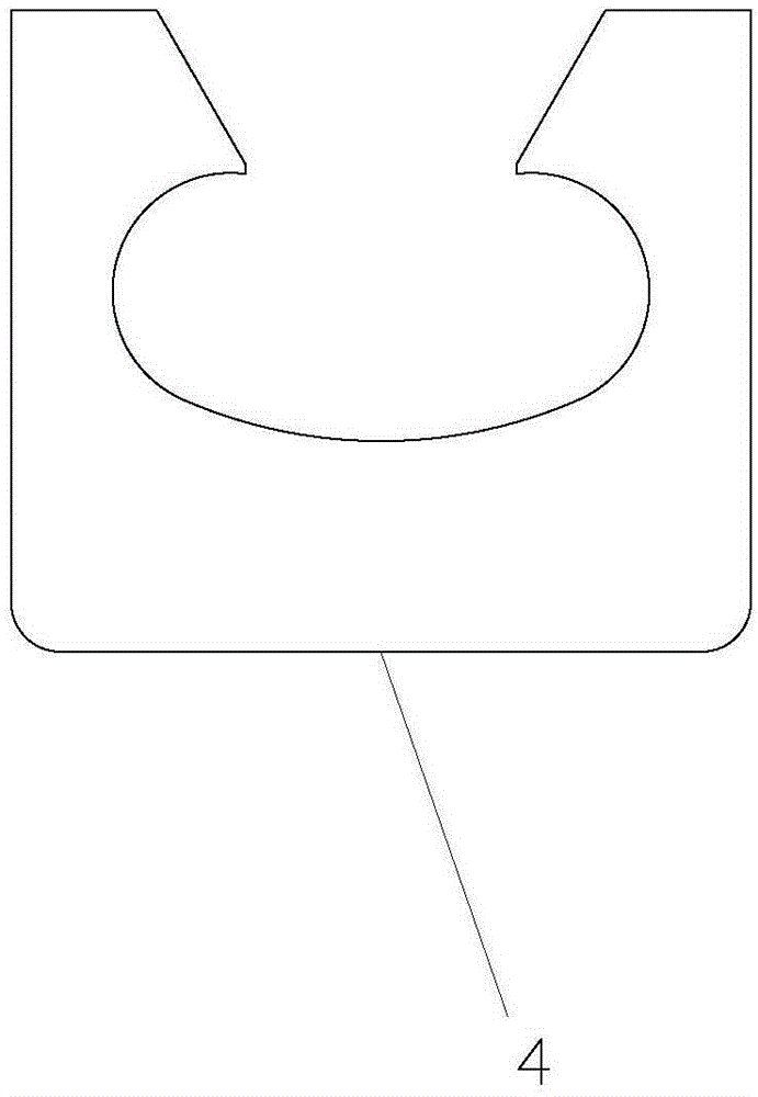
[0011] Below in conjunction with accompanying drawing, the present invention will be further described: figure 1 and figure 2 As shown, in the electroplating workpiece conveying mechanism of the present invention, its gantry trolley 5 is placed on the frame guide rail 6, the trolley can move horizontally along the frame guide rail 6, and the hook 25 can move up and down along the gantry trolley. The frame guide rail 6 is installed on the production line frame 14, the electroplating tank 1 is placed inside the production line frame 14, the workpiece 2 is installed on the hanger 3, and the middle sword hand 23 and the upper sword hand 24 are installed on the hanger 3. 3 is placed on the flying bus seat 4 through the middle sword hand 23, and the flying bus seat 4 is fixed on the production line frame 14 and the conveying chain 12. The shape of the flying bus seat is as image 3 As shown, it can be guaranteed that the conveyor chain 12 will not disengage from the flying bus se...


PUM


Abstract

The invention relates to the technical field of a galvanizer device, and particularly relates to a conveying mechanism of a galvanizer piece. By combining a gantry type trolley with a chain climbing type conveying mechanism, the pieces are conveyed by the trolley in a single-station plating tank. In a multi-station plating tank, the trolley can put the second group of pieces still at the first station without crossing the first group of pieces as the pieces are placed at the first station of the multi-station plating tank by using the ahead trolley and the chain type conveying mechanism automatically moves the first group of pieces to the second station when the trolleys conveys the second group of pieces. Till the stations of the multi-station plating tank are filled with pieces, the trolley at the back of the plating tank moves away the pieces at the last station. By continuously carrying out the electroplating process based on the way, the conveying mechanism of the galvanizer piece disclosed by the invention can be used for not only solving the electroplating problem of ultra-high parts, but improving the efficiency.

Description

technical field [0001] The invention relates to the technical field of electroplating equipment, in particular to an electroplating workpiece conveying mechanism. Background technique [0002] In the electroplating process, the workpiece generally needs to go through dozens of processes in order to complete the entire electroplating process. In the entire process, the conveying method of the workpiece is particularly important. The use of a suitable conveying method is not only related to production efficiency and cost, but also It is related to the smooth realization of the production process. The conveying methods are generally divided into manual and automatic. Manual conveying is generally used in the production process of light weight workpieces and small output. Its advantage is low cost, but it cannot be used for electroplating of large workpieces. Automatic conveying can be used for electroplating of large workpieces, and the conveying machinery automatically convey...

Claims


Application Information

Patent Timeline
Patent Type & Authority Patents(China)
IPC IPC(8): C25D17/28
Inventor 何定华
Owner PLASTIC ENG
Why Eureka
Try Eureka