
Horizontal chrome plating bath and chrome plating method

A chrome plating tank, horizontal technology, applied in the field of electroplating equipment and electroplating, can solve the problems of easy tip discharge, tip discharge, inconvenience, etc., and achieve the effects of saving precious metal materials, improving uniformity and improving efficiency

Pending Publication Date: 2019-10-29
YANTAI NEWSTAR AERO HYDRAULICS
View PDF7 Cites 2 Cited by
  • Summary
  • Abstract
  • Description
  • Claims
  • Application Information

AI Technical Summary

Problems solved by technology

[0002] Most of the existing electroplating tanks are to immerse the material to be electroplated into the electroplating tank from the top of the electroplating tank. This electroplating method is convenient for small or not long plating parts, but for long rods, because it is more than 20m For long rods, this method of electroplating is inconvenient, and because the rods are too long during electroplating, the rods are suspended at both ends, and the upper and lower plating of the rods is not uniform enough. If the vertical plating is performed, the electroplating tank needs to be made The depth is sufficient, and the horizontal type also needs to have sufficient length. If the electroplating tank is too long, the amount of electroplating solution used is too much, and the plating layer is uneven during electroplating, and it is easy to discharge at the tip, requiring a lot of auxiliary tooling;
[0003] Traditional electrochrome plating has uneven coating, which is prone to tip discharge, which requires a lot of shielding tooling to avoid, and is limited by the size of the plating tank, too long piston rod cannot be electroplated

Method used


Image

  • Horizontal chrome plating bath and chrome plating method
  • Horizontal chrome plating bath and chrome plating method
  • Horizontal chrome plating bath and chrome plating method

Examples


Embodiment Construction

[0024] The principles and features of the present invention are described below in conjunction with the accompanying drawings, and the examples given are only used to explain the present invention, and are not intended to limit the scope of the present invention.

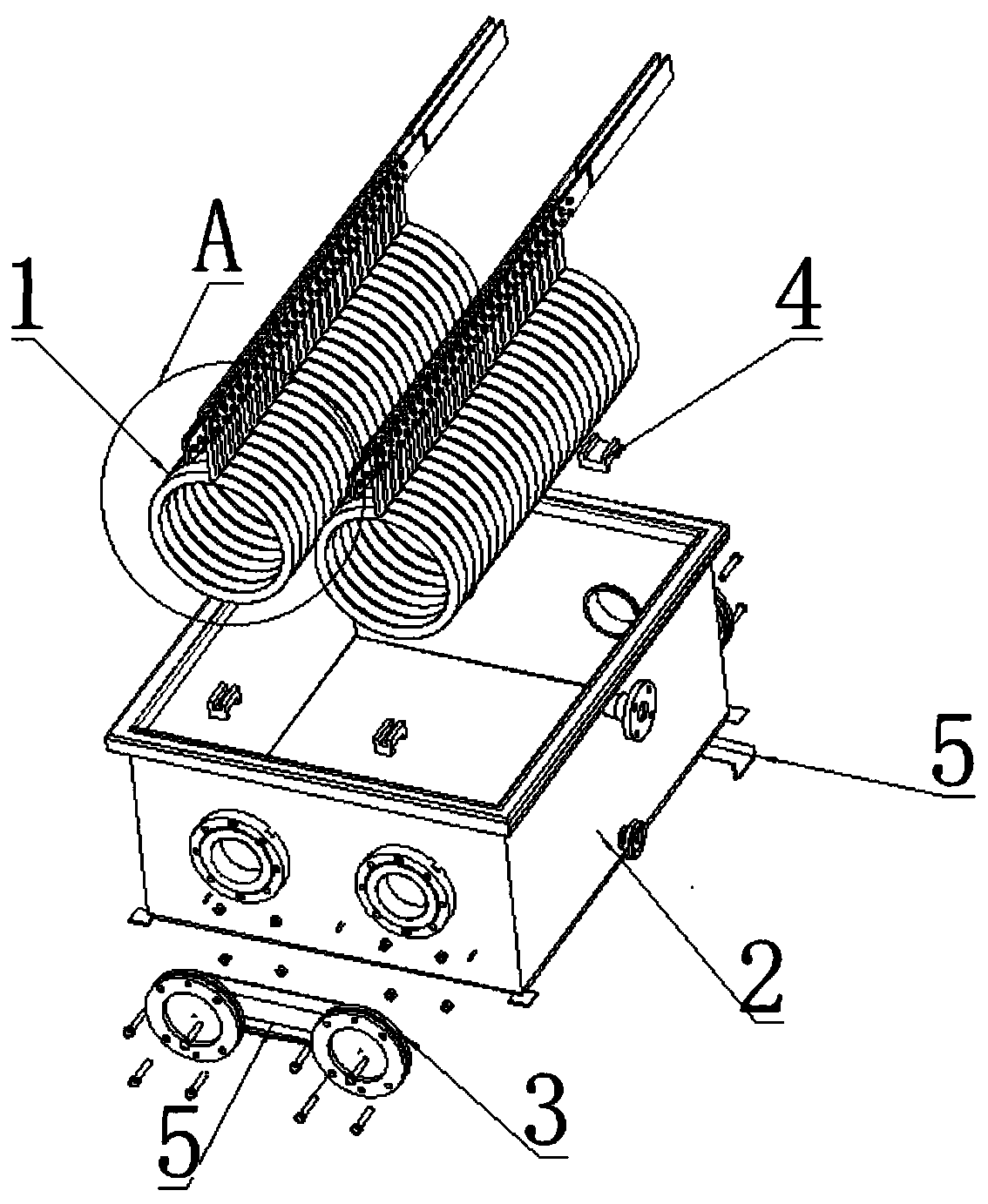
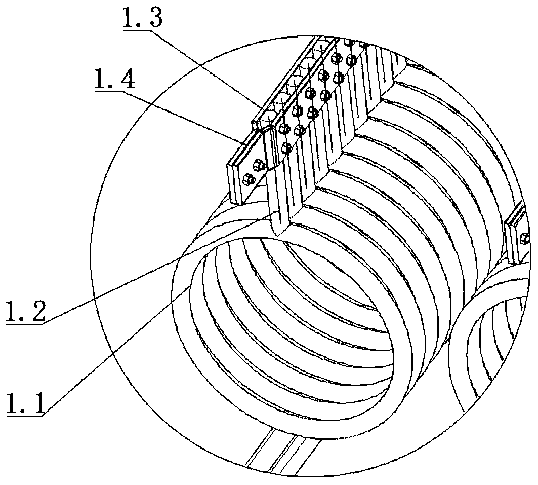
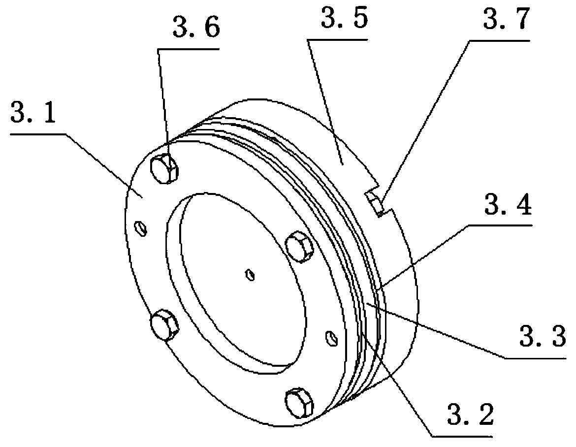
[0025] A kind of horizontal chrome plating tank (see Figure 1-7 ), comprising a tank body 2, a circular passage hole is provided on the side walls at both ends of the tank body 2; a sealing assembly 3 is installed on the side wall outside the passage hole, and a chrome-plated anode assembly 1 is installed on the top of the tank body 2 The chrome-plated anode assembly 1 includes an annular anode ring 1.1 and a suspension beam, the suspension beam includes a pair of beam plates, and the beam plate includes a clamping section 1.3 and fastening sections 1.4 at both ends of the clamping section 1.3; The anode ring 1.1 is provided with a suspension rod 1.2, and the end of the suspension rod 1.2 is fixedly installed betwe...


PUM


Abstract

The invention relates to a horizontal chrome plating bath and a chrome plating method. The horizontal chrome plating bath comprises a bath body. The sidewalls of the two ends of the bath body are provided with circular through holes. Sealing assemblies are mounted on the outer sidewalls of the through holes. A chrome plating anode assembly is mounted on the top of the bath body. The chrome platinganode assembly comprises a plurality of ring-type anode rings and suspension cross beams. Each suspension cross beam comprises a pair of cross beam plates. Each cross beam plate comprises a clampingsection and fastening sections at the two ends of the clamping section. Each anode ring is provided with suspension bars. The ends of the suspension bars are fixedly mounted between the clamping sections of the two cross beam plates of each suspension cross beam. Each sealing assembly comprises an outer sealing flange, an outer seal, an inner sealing flange, an inner seal and a connecting piece. The invention further provides the chrome plating method of the horizontal chrome plating bath. Through the horizontal chrome plating bath and the chrome plating method, the problem that a plating layer is uneven is solved, and a great quantity of precious metal materials can be saved; and the problem existing in plating on long piston rods is solved, multi-length machining on a lot of short pistonrods can be implemented, and the efficiency is improved.

Description

technical field [0001] The invention relates to a horizontal chromium plating bath and a chromium plating method, belonging to the technical field of electroplating devices and electroplating methods. Background technique [0002] Most of the existing electroplating tanks are to immerse the material to be electroplated into the electroplating tank from the top of the electroplating tank. This electroplating method is convenient for small or not long plating parts, but for long rods, because it is more than 20m For long rods, this method of electroplating is inconvenient, and because the rods are too long during electroplating, the rods are suspended at both ends, and the upper and lower plating of the rods is not uniform enough. If the vertical plating is performed, the electroplating tank needs to be made The depth is sufficient, and the horizontal type also needs to have sufficient length. If the electroplating tank is too long, the amount of electroplating solution used i...

Claims


Application Information

Patent Timeline
Patent Type & Authority Applications(China)
IPC IPC(8): C25D17/02C25D17/12C25D7/00C25D3/04
CPCC25D17/02C25D17/12C25D7/00C25D3/04
Inventor 杨明郭敦朋王经国
Owner YANTAI NEWSTAR AERO HYDRAULICS
Learn More