Iodine vapor distributing device with on-line iodine function

A technology of iodine vapor and carrier gas, which is applied in gas and gas/steam mixing, mixer accessories, climate sustainability, etc. It can solve the problem of limited gas filling in steel cylinders, inability to work continuously for a long time, and no mention of online iodine addition, etc. problem, to achieve the effect of reducing the volume and weight of the device, continuous and stable supply for a long time, and reducing the initial iodine loading

Active Publication Date: 2013-05-22
CHINA NUCLEAR POWER ENG CO LTD
View PDF6 Cites 5 Cited by
  • Summary
  • Abstract
  • Description
  • Claims
  • Application Information

AI Technical Summary

Problems solved by technology

The current conventional method is to mix high-purity nitrogen with a certain amount of iodine to prepare iodine vapor with the required concentration, then store it in a high-pressure steel cylinder and transport it to the gas environment. This method can provide continuous and relatively stable iodine vapor, but However, this method has major disadvantages: firstly, the process is complicated, and the cost of preparing and storing iodine vapor is too high; secondly, due to the limited filling gas of the steel cylinder, multiple steel cylinders need to be prepared for long-term continuous use, and the steel cylinders are replaced frequently. Not suitable for long-term continuous use
In the patent documents whose patent application numbers are 9827605.7, 98237990.0 and 02209679.5, a kind of iodine vapor generating device using resistance wire heating is disclosed. Carry the iodine vapor that produces with bubbling method, in order to use; In the patent document that the patent application number is 200710158294.0 also discloses a kind of rapid continuous iodine supply device, describes described iodine supply device with the form of system block diagram, but does not Do any description of the structure of the iodine generator, and the above-mentioned several iodine s

Method used


Image

  • Iodine vapor distributing device with on-line iodine function
  • Iodine vapor distributing device with on-line iodine function
  • Iodine vapor distributing device with on-line iodine function

Examples


Embodiment Construction

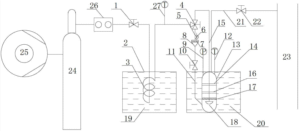
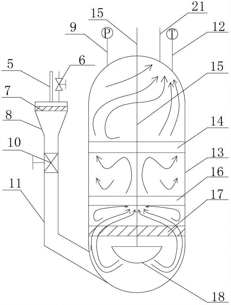
[0026] The present invention will be further described below with reference to accompanying drawing

[0027] like figure 1 As shown, an iodine vapor distribution device capable of adding iodine online is composed of an iodine vapor generating system, a carrier gas preheating system, an online iodine adding system, and pipes and valves connecting each device. The air compressor 25 is connected to the gas cylinder 24, the outlet of the gas cylinder is connected to the flowmeter 26, the flowmeter 26 is connected to the needle valve 1, one end of the spiral tube 3 is connected to the needle valve 1, and the other end is connected to the three-way valve 4 , the other two ends of the three-way valve are respectively connected with the air intake pipe 15 and the balance air pipe 5, the other end of the air intake pipe 15 is connected to the iodine vapor generator, and the other end of the balance air pipe 5 is connected to the charging system. Before the system runs, the air compres...


PUM


Abstract

The invention provides an iodine vapor distributing device with an on-line iodine feeding function. The iodine vapor distributing device comprises an iodine vapor generating system, a carrier gas preheating system, an online iodine feeding system, pipelines and valves, wherein the pipelines and the valves are used for connecting all the systems; the carrier gas preheating system comprises an air compressor, a gas storage cylinder, a spiral pipe and a first water bath; the iodine vapor generating system comprises an iodine pool, an upper gas distributing plate, a carrier gas pipe, a lower gas distributing plate, a carrier gas diffusion nozzle and a second water bath; and the online iodine feeding system comprises a feeding hopper, a spherical valve and a feeding pipe. The iodine vapor distributing device provided by the invention is economic and reliable, can meet requirements on continuous operation under different working conditions, can be applied to performance tests of a safety housing filtering and discharging system, and is also suitable for other fields such as chemical industry needing continuous iodine feeding for a long time.

Description

technical field [0001] The invention relates to a device for generating and distributing iodine vapor. Background technique [0002] The containment filter and discharge system is a system set up to ensure the integrity of the containment. When a serious accident of core meltdown occurs, the containment filter and discharge system will release the gas in the containment by active pressure relief. After washing and filtering, it is discharged into the environment to achieve the purpose of preventing the overpressure of the containment vessel, reducing the release of radioactive substances into the environment as much as possible, and reducing the radiation dose of the public from accidents. As one of the fission products, 131I is easily leaked from defective fuel elements and is highly radioactive. The amount released into the environment has been used as a standard to measure the severity of accidents. In order to reduce the consequences of serious accidents , the radioacti...

Claims


Application Information

Patent Timeline
IPC IPC(8): B01F5/00B01F3/02B01F15/06G21C17/00B01F23/10
CPCY02E30/30
Inventor 谷海峰孙中宁王军龙阎昌琪孙立成曹夏昕王建军范广铭
Owner CHINA NUCLEAR POWER ENG CO LTD
Why Eureka
Try Eureka