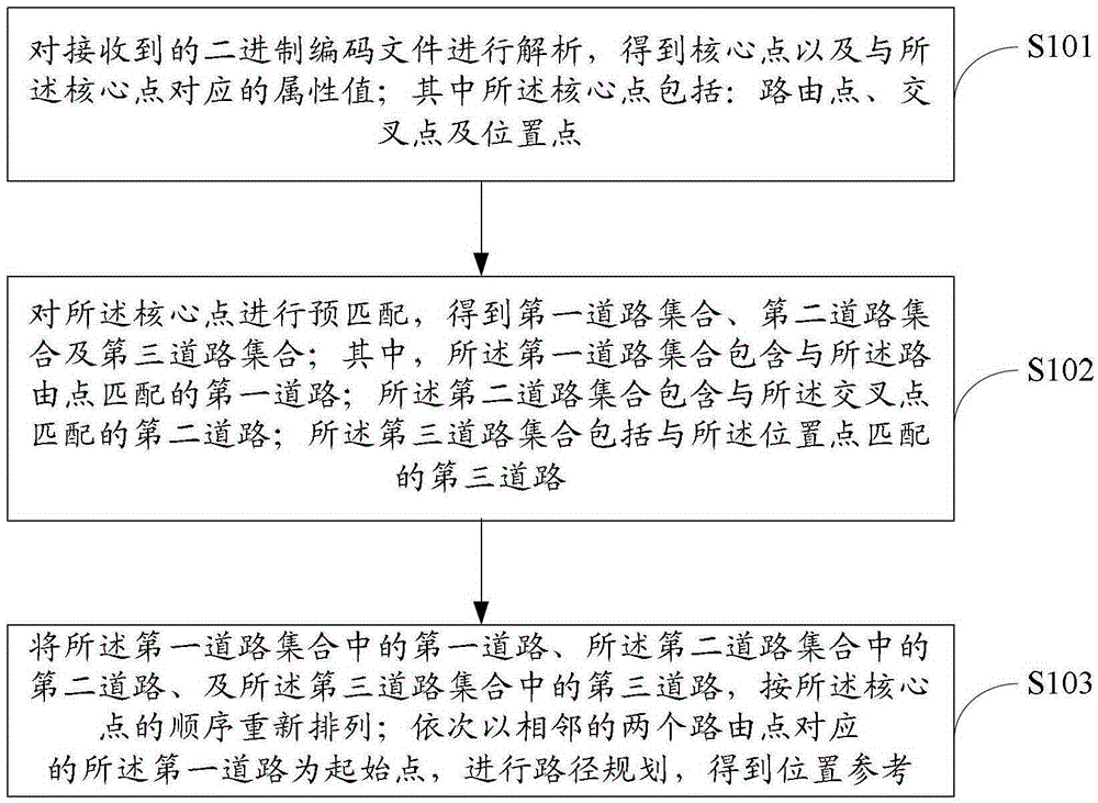
Method and device for dynamic position decoding
A dynamic location and location point technology, applied in special data processing applications, instruments, electrical digital data processing, etc., can solve the problems of large occupied space, limited corresponding table capacity, and low road network accuracy.
- Summary
- Abstract
- Description
- Claims
- Application Information
AI Technical Summary
Problems solved by technology
Method used
Image
Examples
Embodiment 1
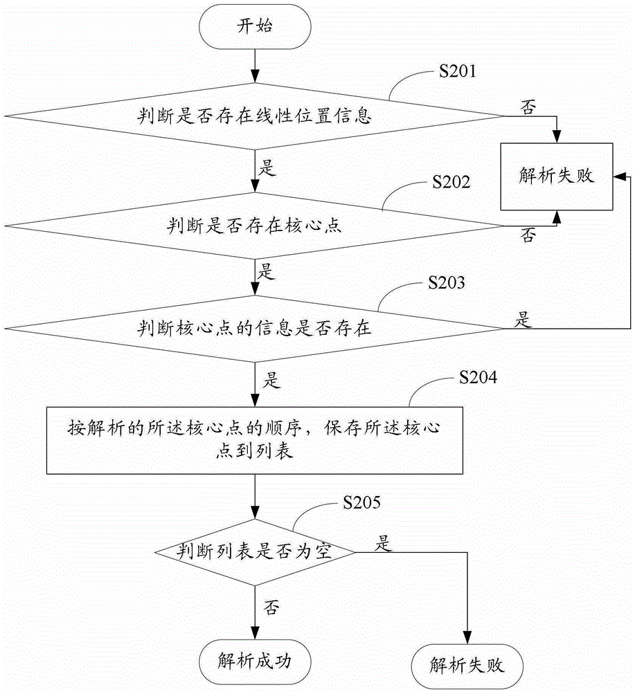
[0042] Embodiment one, such as figure 2 As shown, the parsing of the received binary coded file may specifically be:
[0043] S201. Parse the binary coded file to determine whether there is linear position information, and if so, go to S202; otherwise, return parsing failure.
[0044] S202. Analyze the linear position information to determine whether there is a core point, and if so, proceed to S203; otherwise, return analysis failure.
[0045] S203, determine whether the coordinates of the core point, IPsignature (intersection label), RPSignature (routing point label), SRSignature (branch label), and the attribute value corresponding to the core point exist, if exist, enter S204, otherwise, return Parsing failed.
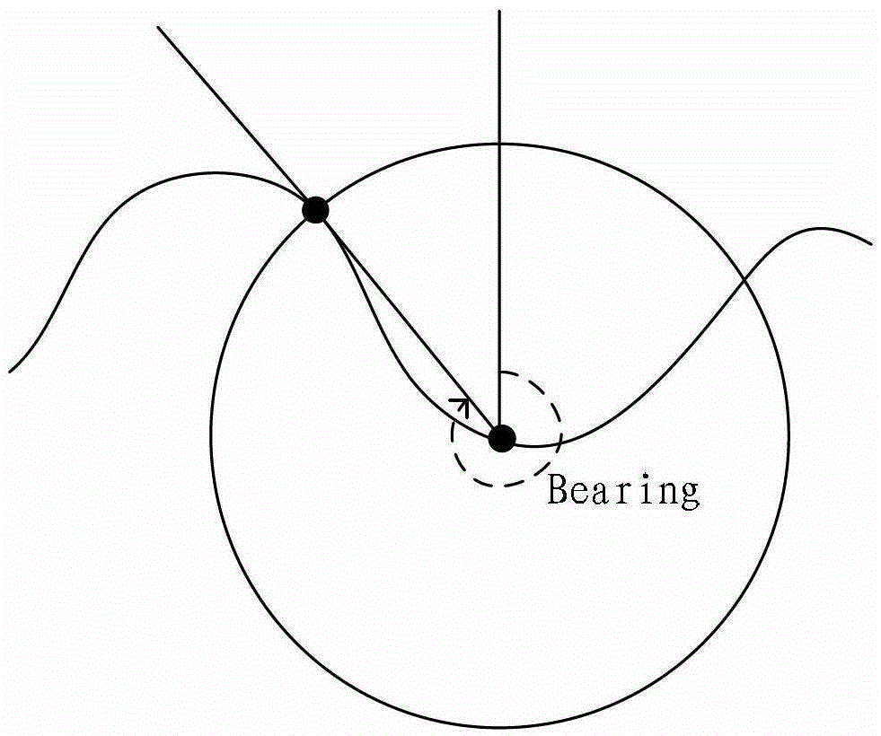
[0046] The IPsignature records the attributes of the road, such as: road function level, road name, etc.; the RPSignature records the BR (bearing, axis angle) attribute, PD attribute (distance between adjacent RPs), etc.; the SRSignature The CA (connectangle, c...
Embodiment 2
[0061] Embodiment two, such as Figure 5 As shown, according to the arrangement order of the routing points in the core points, for each routing point, pre-matching the routing points may specifically include the following steps:
[0062] S301. In the circular search area with the position of the routing point as the center in the map and the first preset value as the radius, search for the first road intersecting the circular area; If the first road intersecting the circular area is found, proceed to S302; if the first road intersecting the circular area is found, proceed to S303.
[0063] Wherein the first preset value may be, for example, 150 meters.
[0064] S302. Double the first preset value, that is, take the position of the routing point as the center of the circle and double the first preset value as the radius of the circular search area, and search for intersections with the circular area the first road; if the first road intersecting the circular area is found, g...
Embodiment 3
[0081] Embodiment three, such as Figure 6 As shown, according to the arrangement order of the intersection in the core point, for each intersection, pre-matching the intersection may specifically include the following steps:
[0082] S401. Search for a second road intersecting the circular area in the circular search area with the position of the intersection point as the center in the map and a second preset value as the radius; If the second road intersecting the circular area is found, proceed to S402; if the second road intersecting the circular area is found, proceed to S403.
[0083] S402. Double the second preset value, that is, take the location of the routing point as the center of the circle and double the second preset value as the radius of the circular search area, and search for intersections with the circular area the second road; if the second road intersecting the circular area is found, go to S403; otherwise, return failure.
[0084] S403. Save the searche...
PUM
 Abstract
Description
Claims
Application Information
 - Generate Ideas
- Intellectual Property
- Life Sciences
- Materials
- Tech Scout
- Unparalleled Data Quality
- Higher Quality Content
- 60% Fewer Hallucinations
Browse by: Latest US Patents, China's latest patents, Technical Efficacy Thesaurus, Application Domain, Technology Topic, Popular Technical Reports.
© 2025 PatSnap. All rights reserved.Legal|Privacy policy|Modern Slavery Act Transparency Statement|Sitemap|About US| Contact US: help@patsnap.com


