
Detection method for frequency hopping changes of crystal oscillator

A detection method and crystal oscillator frequency technology, applied in the direction of frequency measurement devices, etc., can solve the problems of communication system clock loss of lock, increased crystal oscillator production cost, long frequency monitoring time, etc., to improve judgment accuracy, reduce intervention, and facilitate operation Effect

Inactive Publication Date: 2013-05-15
HEBEI FAREAST COMM SYST ENG
View PDF3 Cites 9 Cited by
  • Summary
  • Abstract
  • Description
  • Claims
  • Application Information

AI Technical Summary

Problems solved by technology

The sharp jump of the output frequency of the crystal oscillator with the temperature may cause serious problems such as clock loss of the communication system, abnormal communication, or increased measurement error.
The current international common detection method is to put the crystal oscillator in the high and low temperature control box, and monitor the frequency output of the crystal oscillator with the temperature change curve in real time to see if there is a frequency jump. However, this solution requires high hardware and takes a long time for frequency monitoring, which seriously increases the Crystal production cost
In addition, there are also detection schemes that use fixed collection of a few discrete temperature point frequency outputs or random inspection of a batch of products, which will inevitably lead to some crystal oscillators with frequency hopping characteristics entering the market, affecting product quality

Method used


Image

  • Detection method for frequency hopping changes of crystal oscillator

Examples


Embodiment Construction

[0017] The present invention will be further described in detail below in conjunction with the accompanying drawings and specific embodiments.

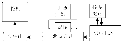
[0018] like figure 1 Shown is a schematic structural diagram of the detection device of the present invention. The existing test fixture is adopted, and the test fixture is respectively connected with a crystal oscillator power supply circuit and a frequency meter, and the frequency meter is connected with an industrial computer through a serial interface. A heater is arranged above the shell of the crystal oscillator, and the heating process of the heater to the crystal oscillator is automatically controlled by a temperature control circuit. When testing, it takes about 90 seconds for the crystal oscillator to naturally heat up from low temperature to room temperature at room temperature, that is, the heating rate is about 0.7°C / 1sec. When the gate time of the frequency meter is set to 150ms, 9 frequencies can be evenly collected pe...


PUM


Abstract

The invention discloses a detection method for frequency hopping changes of a crystal oscillator. The detection method comprises the following steps: step 1, the crystal oscillator is cooled in a temperature-controlled cabinet to reach a low temperature; step 2, at a room temperature, a frequency output curve of the crystal oscillator heated gradually from the low temperature to the room temperature is formed through a test, fitting software is utilized for judging whether the crystal oscillator has the frequency hopping changes; and step 3, a heater is utilized for heating the crystal oscillator quickly to reach the highest working temperature of the crystal oscillator, a frequency output curve of the crystal oscillator from the room temperature to the high temperature is formed through a test, and whether the frequency output of the crystal oscillator has the hopping phenomenon is judged. The detection method for the frequency hopping changes of the crystal oscillator has the advantages of being simple in operation, high in detection speed, accurate and reliable in judgment, high in detection efficiency and the like, and is especially suitable for detection of performance, related to the frequency hopping changes, of the crystal oscillator in a mass production process of the crystal oscillator.

Description

technical field [0001] The invention relates to a technique for process control optimization and production efficiency improvement in the crystal oscillator production process, in particular to a detection method for crystal oscillator frequency jump. Background technique [0002] At present, the output frequency of some crystals will produce a frequency jump phenomenon at a specific temperature point. Internationally, this phenomenon is generally expressed by crystal DIP characteristics. A crystal oscillator made of a crystal with frequency hopping also has the characteristic of frequency hopping at a specific temperature point. The sharp jump of the output frequency of the crystal oscillator with temperature may cause serious problems such as clock loss of the communication system, abnormal communication, or increased measurement error. The current international common detection method is to put the crystal oscillator in the high and low temperature control box, and monit...

Claims


Application Information

Patent Timeline
IPC IPC(8): G01R23/02
Inventor 储文淼汪春晖赵富赵旺魏鹏
Owner HEBEI FAREAST COMM SYST ENG
Learn More