
Sucker type rotary table

A suction cup and rotating shaft technology, applied in the direction of conveyor objects, furnaces, lighting and heating equipment, etc., can solve the problems of broken glass, low production efficiency, troubles, etc., and achieve the effect of low cost, simple structure and convenient use

Inactive Publication Date: 2013-05-15
LINAN TIANYU MACHINERY EQUIP
View PDF6 Cites 12 Cited by
  • Summary
  • Abstract
  • Description
  • Claims
  • Application Information

AI Technical Summary

Problems solved by technology

[0003] In the actual production of glass, the glass usually needs to be polished on the corners, and then when the left and right sides are polished, and then the front and rear sides need to be changed, the staff needs to carry it manually, which is very troublesome, low in production efficiency, and prone to grinding. broken glass accident

Method used


Image

  • Sucker type rotary table
  • Sucker type rotary table
  • Sucker type rotary table

Examples


Embodiment Construction

[0017] For ease of illustration, the present invention is described in detail by the following specific embodiments and accompanying drawings.

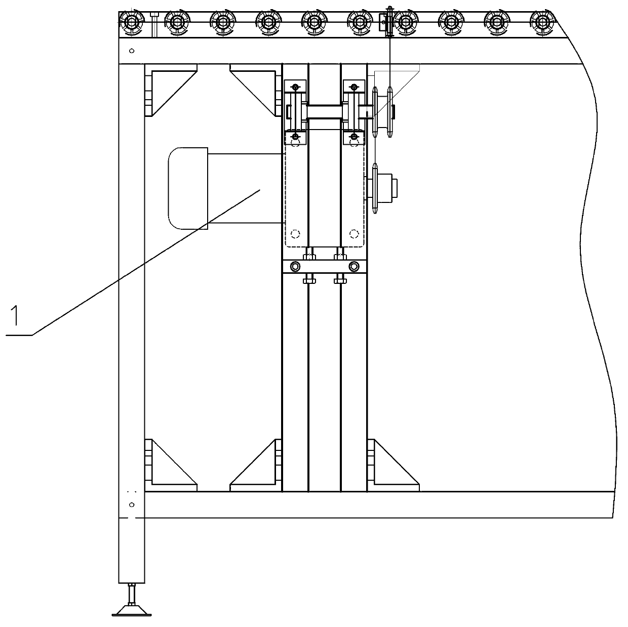
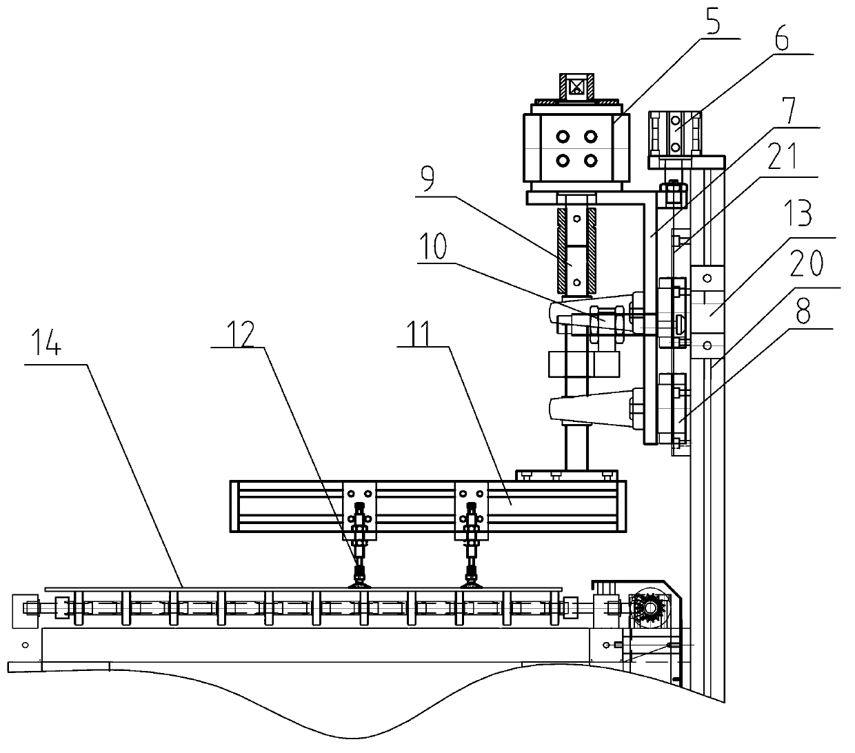
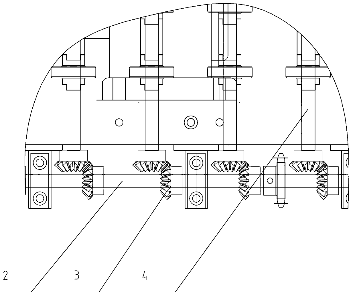
[0018] Such as figure 1 , figure 2 , image 3 , Figure 4 As shown, the suction cup turntable of this embodiment includes a column 20, a rotating mechanism and a conveying mechanism. The rotating mechanism is installed on the column 20 and is located on the conveying mechanism. The rotating mechanism includes a rotating cylinder 5 and a rotating shaft arranged at the lower end of the rotating cylinder 5. 9, and the suction cup frame 11 that is located at the bottom of the rotating shaft 9, and the suction cup 12 installed on the lower side of the suction cup frame 11, the suction cup 12 is connected to the vacuum generator, and a hydraulic buffer 10 is installed between the rotating shaft 9 and the column 20. The hydraulic buffer bumper 13 used in conjunction with the hydraulic buffer 10; the conveying mechanism includes a motor a...


PUM


Abstract

A sucker type rotary table comprises an upright column, a rotating mechanism and a conveying mechanism. The rotating mechanism is mounted on the upright column and also located on the conveying mechanism. The rotating mechanism comprises a rotating cylinder, a rotating shaft disposed at the lower end of the rotating cylinder, a sucker frame arranged at the bottom end of the rotating shaft and a sucker installed on the lower side of the sucker frame. The sucker is communicated with a vacuum generator, and a hydraulic buffer and a hydraulic buffer bump used with the hydraulic buffer in a matched mode are mounted between the shafting shaft and the upright column. The conveying mechanism comprises a motor, a conveying roller transmission reducer, a conveying roller transmission shaft connected with the conveying roller transmission reducer through a chain and a conveying roller. A plurality of transmission gears are disposed on the conveying roller transmission shaft, and gears meshed with the transmission gears are arranged at one end of the conveying roller. The sucker type rotary table is simple in structure, convenient to use, good in use effect and low in cost.

Description

technical field [0001] The invention relates to a suction cup turntable. Background technique [0002] Glass: A relatively transparent solid substance that forms a continuous network structure when molten, and a silicate non-metallic material that gradually increases in viscosity and hardens during cooling. The composition of ordinary glass chemical oxides (Na2O·CaO·6SiO2), the main component is silicon dioxide. Widely used in buildings, used for wind and light transmission, belongs to the mixture. [0003] In the actual production of glass, the glass usually needs to be polished on the corners, and then when the left and right sides are polished, and then the front and rear sides need to be changed, the staff needs to carry it manually, which is very troublesome, low in production efficiency, and prone to grinding. Broken glass accident. Contents of the invention [0004] The technical problem to be solved by the present invention is to provide a sucker turn...

Claims


Application Information

Patent Timeline
Patent Type & Authority Applications(China)
IPC IPC(8): B65G49/06B65G47/91
Inventor 尹青
Owner LINAN TIANYU MACHINERY EQUIP
Learn More