Image coding method and device, image decoding method and device
An image encoding and image decoding technology, which is applied in the field of image encoding and decoding, can solve the problem of inconsistency between the Z axis and the camera orientation, and achieve the effect of reducing the amount of code
- Summary
- Abstract
- Description
- Claims
- Application Information
AI Technical Summary
Problems solved by technology
Method used
Image

Examples
no. 1 approach
[0118] [First Embodiment: Image Coding Device]
[0119] First, a first embodiment will be described.
[0120] figure 1 It is a block diagram showing the configuration of the image encoding device according to the first embodiment of the present invention.
[0121] Such as figure 1 As shown, the image encoding device 100 includes: an encoding target frame input unit 101, an encoding target frame memory 102, an object number setting unit 103, an object pixel value setting unit 104, an object pixel value encoding unit 105, A subject map generation unit 106 , a subject map encoding unit 107 , a predicted image generation unit 108 , an image signal encoding unit 109 , and a multiplexing unit 110 .
[0122] The encoding target frame input unit 101 inputs an image frame to be encoded.
[0123] The encoding target frame memory 102 stores input encoding target frames.
[0124] The subject number setting unit 103 sets the number of subjects included in a processing area of a pr...
no. 2 approach
[0228] [Second Embodiment: Image Decoding Device]
[0229] Next, a second embodiment of the present invention will be described.
[0230] Figure 10 It is a block diagram showing the structure of the image decoding device of the second embodiment.
[0231] Such as Figure 10 As shown, the image decoding device 200 includes: a coded data input unit 201, a coded data memory 202, a separation unit 203, a subject number setting unit 204, a subject map decoding unit 205, a subject pixel value decoding unit 206, A predicted image generation unit 207 and an image signal decoding unit 208 .
[0232] The encoded data input unit 201 inputs encoded data of an image frame to be decoded.
[0233] The coded data memory 202 stores input coded data.
[0234] The separation unit 203 separates the multiplexed encoded data into a plurality of encoded data in which different information is encoded.
[0235] The subject number setting unit 204 sets the number of subjects included in a proces...
example 1
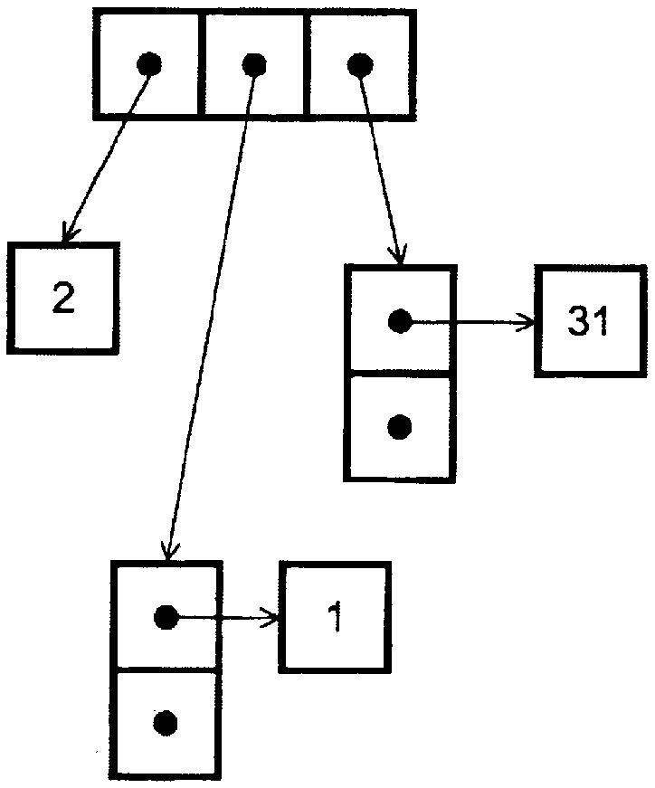
[0305] Figure 16A , 16B It is a diagram showing an example 1 of the data structure of the additional information used for generating the predicted image.
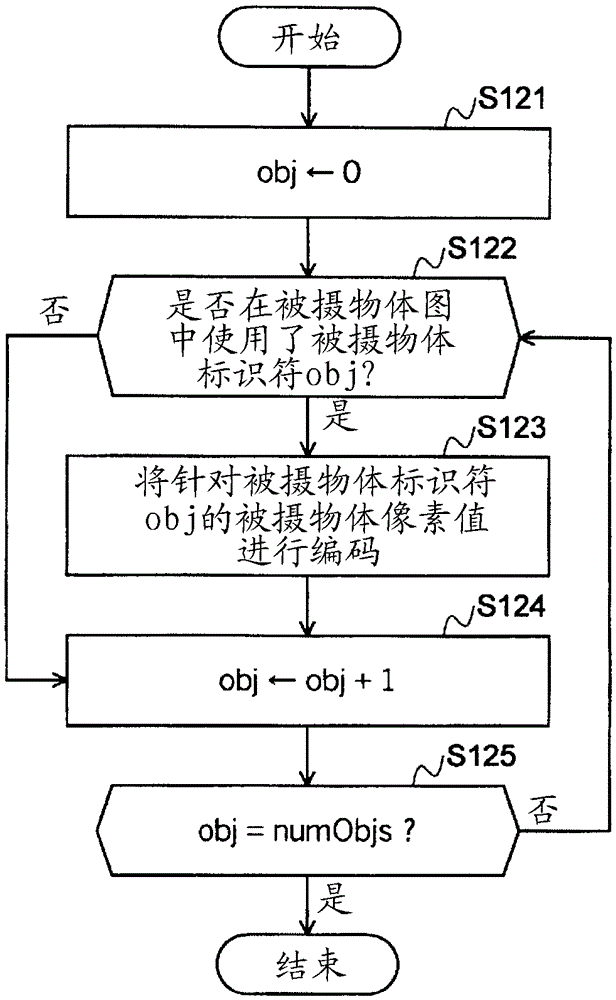
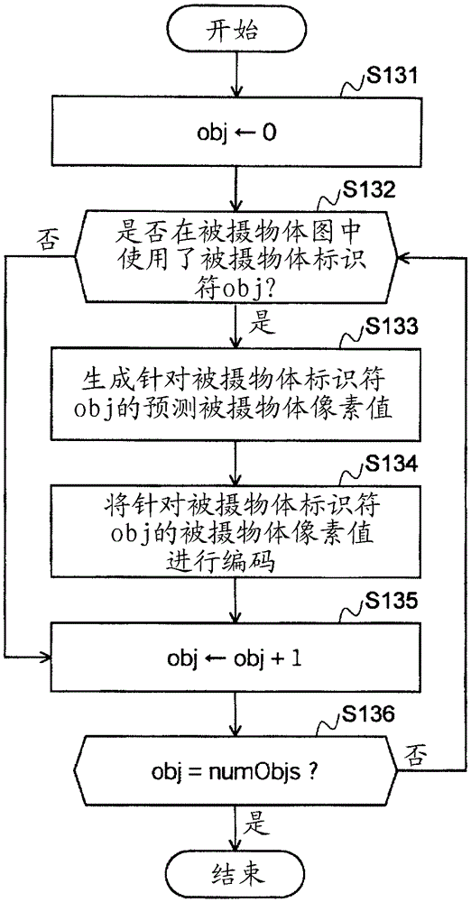
[0306] For the prediction of the image signal of the encoding / decoding object, such as Figure 16A As shown in , the number of subjects, the subject map, and the subject pixel value of each subject identifier are set.
[0307] The number N of subjects is an integer. The subject map is an integer sequence of 0 to N−1 having the same length as the number of pixels in a block. In the case of no prediction, the pixel value of the object is an integer without encoding, and in the case of prediction, the pixel value of the object is an integer with encoding (consider negative numbers).
[0308] Figure 16B A specific example of additional information is shown. Although the number of subjects is four, none of the pixels whose subject identifier is 2 exists in the subject map. Therefore, the data of the subject pixel value ...
PUM
 Abstract
Description
Claims
Application Information
 - R&D
- Intellectual Property
- Life Sciences
- Materials
- Tech Scout
- Unparalleled Data Quality
- Higher Quality Content
- 60% Fewer Hallucinations
Browse by: Latest US Patents, China's latest patents, Technical Efficacy Thesaurus, Application Domain, Technology Topic, Popular Technical Reports.
© 2025 PatSnap. All rights reserved.Legal|Privacy policy|Modern Slavery Act Transparency Statement|Sitemap|About US| Contact US: help@patsnap.com