
Single-inductor intelligent photovoltaic module and control method and photovoltaic system based on single-inductor intelligent photovoltaic module

A photovoltaic module and control method technology, applied in the field of solar photovoltaic power generation research, can solve problems such as failure to reach the maximum output power point, poor system reliability, system oscillation, etc., and achieve the effect of eliminating energy loss and other problems

Inactive Publication Date: 2013-05-08
XI AN JIAOTONG UNIV
View PDF4 Cites 13 Cited by
  • Summary
  • Abstract
  • Description
  • Claims
  • Application Information

AI Technical Summary

Problems solved by technology

[0005] 3) The output characteristics of the entire system appear "multi-peak" characteristic curves, which affect the normal operation of grid-connected equipment;
[0006] 4) The system oscillates, which will affect the stability of the power grid in severe cases
[0007] 5) In severe cases, it will affect the power quality of the entire grid
This method is based on high-precision detection links, precise regulator design and complex control procedures. The reliability of the system is poor, and it cannot be widely adopted by the industry at present.
Moreover, even if the global maximum power point of the entire photovoltaic system can be found through some complex algorithm, it still cannot reach the maximum output power point of the system theory, which seriously affects the output efficiency of the entire photovoltaic solar energy system, so it does not fundamentally solve the problem

Method used


Image

  • Single-inductor intelligent photovoltaic module and control method and photovoltaic system based on single-inductor intelligent photovoltaic module
  • Single-inductor intelligent photovoltaic module and control method and photovoltaic system based on single-inductor intelligent photovoltaic module
  • Single-inductor intelligent photovoltaic module and control method and photovoltaic system based on single-inductor intelligent photovoltaic module

Examples


Embodiment Construction

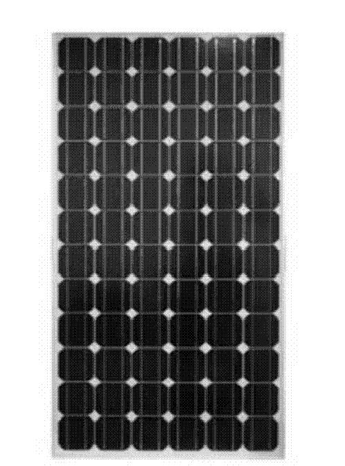
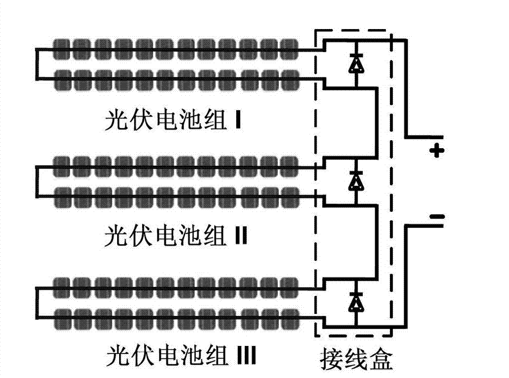
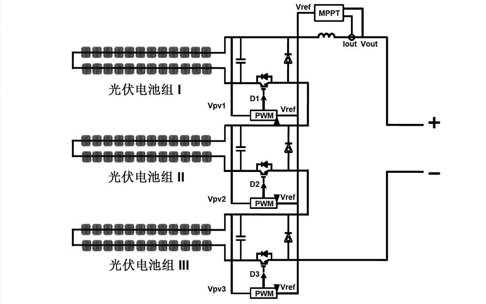
[0028] Conventional photovoltaic solar panels (see figure 1 The output of each photovoltaic cell group in ) is connected in series, so the output current must be consistent, and in the case of shading or uneven illumination, a "hot spot" phenomenon will occur, which will cause damage to the solar panel. Therefore, the common practice in the industry is to connect a diode in antiparallel to each photovoltaic cell group (see figure 2 ), through the bypass method to avoid damage to the battery pack due to inconsistent output current. This method prolongs the life of the solar panel to a certain extent, but also gives up the energy generated by the shaded battery pack, and also seriously affects the efficiency and stability of the solar system. The present invention proposes a photovoltaic module based on a distributed maximum power tracking structure, which uses multiple sets of power electronic switches, capacitors, and inductors to replace the parallel diodes in the junction ...


PUM


Abstract

The invention discloses a single-inductor intelligent photovoltaic method, a control method and a photovoltaic system based on the photovoltaic module. The photovoltaic module comprises photovoltaic battery packs, electronic power switch arm pairs, capacitors, inductors and a maximum power tracing unit, wherein a switching network is formed by parallel connection of each electronic power switch arm pair and each capacitor, each switching network is in parallel connection with two ends of each photovoltaic battery pack, output ends of the switching networks are sequentially in serial connection and then are in serial connection with the unification output inductors, each switching network is provided with a closed control circuit, the maximum power tracing unit collects current and voltage signals output by a photovoltaic optimizer and then transmits the signals to each control circuit of each switching network to guarantee that each photovoltaic battery pack works on the maximum power output point under any external lighting conditions, and output power of a photovoltaic solar system under mismatch lighting conditions is extremely improved.

Description

【Technical field】 [0001] The invention belongs to the research field of solar photovoltaic power generation, and in particular relates to a circuit structure of a novel intelligent photovoltaic module and a control method thereof. 【Background technique】 [0002] As a clean, non-polluting, inexhaustible and inexhaustible renewable energy, solar energy has attracted more and more attention from the society in today's rapid development. However, due to its high investment costs, low output efficiency, and unstable output energy, how to maximize the use of energy generated by photovoltaic solar panels has become a decisive factor in determining the development of the photovoltaic industry. The solar panel is the core part of the solar power generation system, and it is also the most valuable part of the solar power generation system. Its function is to convert the radiation ability of the sun into electrical energy, which is supplied to the grid or users. The quality and cost ...

Claims


Application Information

Patent Timeline
Patent Type & Authority Applications(China)
IPC IPC(8): H02N6/00H02M3/155H02S40/30
CPCY02E10/56
Inventor 王丰卓放
Owner XI AN JIAOTONG UNIV
Learn More