
Magnetic coupling unit and magnetic coupling system

A technology of magnetic coupling and magnetic device, applied in the field of magnetic coupling system, can solve the problems of transmission efficiency (reduced feeding efficiency, etc., to achieve the effect of reducing energy loss and enhancing magnetic coupling)

Active Publication Date: 2013-05-08
SONY CORP
View PDF6 Cites 3 Cited by
  • Summary
  • Abstract
  • Description
  • Claims
  • Application Information

AI Technical Summary

Problems solved by technology

Also, even if the axial alignment is insufficient, the transmission efficiency (feed efficiency) is less likely to decrease

Method used


Image

  • Magnetic coupling unit and magnetic coupling system
  • Magnetic coupling unit and magnetic coupling system
  • Magnetic coupling unit and magnetic coupling system

Examples


no. 1 example

[0038] 1. First Embodiment (First Example of Contactless Power Feeding System Including Coupling Reinforcing Section in Primary Side Unit)

no. 2 example

[0039] 2. Second Embodiment (Second Example of Contactless Power Feeding System Including Coupling Reinforcing Section in Primary Side Unit)

no. 3 example

[0040] 3. Third Embodiment (Third Example of Contactless Power Feeding System Including Coupling Reinforcing Section in Primary Side Unit)

[0041] 4. Modification (example of non-contact power feeding system including coupling reinforcement in secondary side unit or other unit)

[0042] 5. Other variants (an example of a magnetic coupling system instead of a contactless feeding system)

[0043] [first embodiment]

[0044] [General Configuration of Feed System 4]

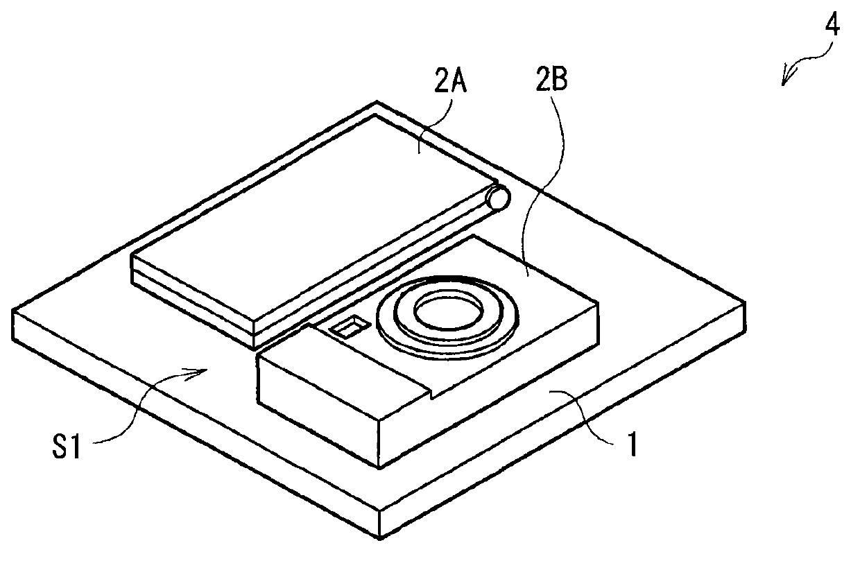
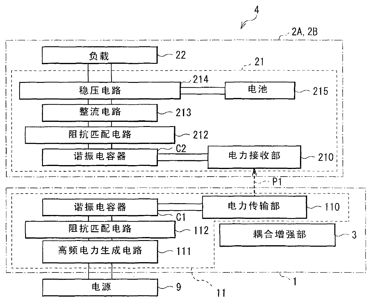
[0045] figure 1 An example of an appearance configuration of a feed system (feed system 4 ) as a magnetic coupling system according to the first embodiment of the present invention is illustrated. figure 2 A block diagram configuration example of the feed system 4 is illustrated. The power feeding system 4 is a system (non-contact power feeding system) that performs non-contact power transmission (power supply, or power feeding) using a magnetic field (using magnetic resonance, etc., hereinafter). The feed sys...


PUM


Abstract

There are provided a magnetic coupling unit and a magnetic coupling system which are capable of reducing energy loss when operations using magnetic coupling between magnetic devices are performed. The magnetic coupling unit includes: one or more magnetic devices each capable of being magnetically coupled with other magnetic device in other unit; and one or more coupling reinforcing sections each reinforcing the magnetic coupling.

Description

technical field [0001] The invention relates to a magnetic coupling unit having magnetic means such as coils, and a magnetic coupling system comprising a plurality of such magnetic coupling units. Background technique [0002] In recent years, power feeding systems (non-contact power feeding systems, wireless charging systems) that perform non-contact power supply (power transmission) for CE devices (Consumer Electronics) such as mobile phones and mobile music players have attracted attention . Therefore, charging can be started by placing the electronic unit (secondary side unit) on the charging tray (primary side unit) without inserting (connecting) a connector of a power source such as an AC adapter into a unit. In other words, terminal connections between the electronic unit and the charging tray are unnecessary. [0003] As a method of performing non-contact power supply in this way, an electromagnetic induction method (for example, Japanese Unexamined Patent Applicat...

Claims


Application Information

Patent Timeline
Patent Type & Authority Applications(China)
IPC IPC(8): H02J17/00H01F38/14
CPCH02J17/00H02J7/025H02J7/00045H02J50/50H02J7/0044H02J50/12H02J50/70H01F38/14
Inventor 宮本宗
Owner SONY CORP
Learn More