
Multilevel automatic voltage reactive power control system AVC coordination control method

An automatic voltage and coordinated control technology, which is applied in the field of power system, can solve the problems of strong coupling between voltage and reactive power, which makes it difficult to realize effective partitioning and complex operation mode, so as to reduce upgrading work, save power grid investment, and improve economic benefits.

Active Publication Date: 2013-05-08
CHINA ELECTRIC POWER RES INST +2
View PDF4 Cites 10 Cited by
  • Summary
  • Abstract
  • Description
  • Claims
  • Application Information

AI Technical Summary

Problems solved by technology

The problems with this model lie in the effectiveness and rapidity of the partition algorithm when faced with massive data, and the energy efficiency ratio between the partitioned reactive power optimization results and the overall reactive power optimization results, etc.
[0007] With the gradual construction of UHV power grids, UHV substations will gradually penetrate into some provincial power grids, and will realize the UHV AC-DC hybrid connection of large regional power grids. The entire power grid covers a wide area and has complex operation modes.
The voltage and reactive power automatic control method based on power grid partitioning will face the problem that the voltage and reactive power coupling between UHV partitions is strong and it is difficult to achieve effective partitioning. Higher requirements are put forward for the convergence and rapidity of the program

Method used


Image

  • Multilevel automatic voltage reactive power control system AVC coordination control method
  • Multilevel automatic voltage reactive power control system AVC coordination control method
  • Multilevel automatic voltage reactive power control system AVC coordination control method

Examples


Embodiment Construction

[0031] The specific steps of a multi-stage automatic voltage and reactive power control system (AVC) coordinated control method are as follows:

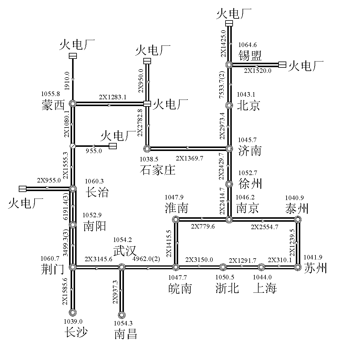
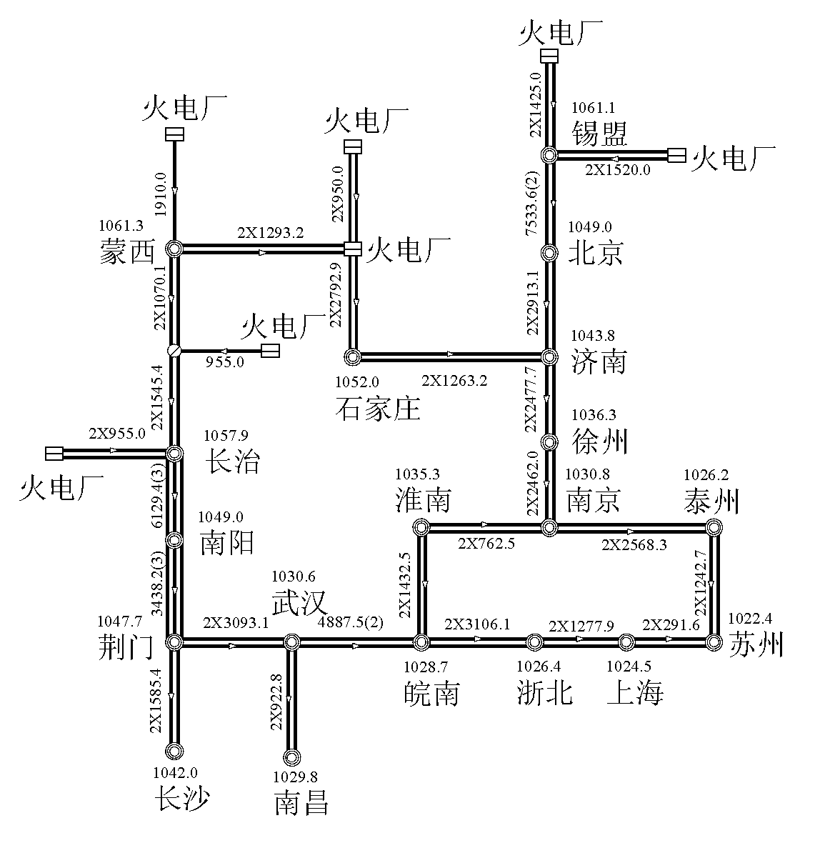
[0032] (1) Propose a preliminary plan for the transformer tap position of each UHV substation through the calculation and analysis of the parallel overvoltage of each line of the UHV planned grid; through the voltage adjustment and reactive power stratification of typical large and small loads Calculation and analysis of balance control flexibility to further determine the transformer tap position scheme of each UHV substation; the transformer tap position is included in the AVC control system as a boundary condition, and the transformer tap cannot be adjusted during the control process of the AVC system;

[0033] (2) Introduce formula (1) into the OPF analysis and calculation of the power grid to calculate the optimal operating voltage value of each UHV busbar;

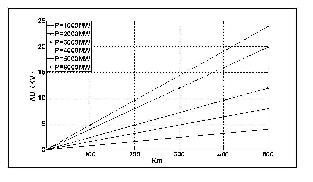
[0034] min Δ U j ...


PUM


Abstract

The invention provides a multilevel automatic voltage reactive power control system AVC coordination control method. A multilevel AVC system coordination control method scheme is disclosed aiming at ultra-high voltage and 500 kV large scale interconnected network voltage reactive power control requirements and current situations of 500kV power grid AVC systems. An ultra-high voltage power grid having the task of networking and large scale power transmission establishes a primary AVC system to carry out AVC control tasks of an ultra-high voltage level power grid, and cooperative control of an existing 500kV power grid AVC system can be achieved through reasonable layering control. The multilevel automatic voltage reactive power control system can achieve reactive power real-time layering balance control of an ultra-high voltage layer face and 500kV power layer face, obviously reduces grid loss, improves power grid running economical benefits, simultaneously achieve effective connection of the ultra-high voltage power grid AVC system and a provincial level power grid AVC system, reduces upgrading development of an existing provincial level power grid AVC system to greatest extend and greatly saves power grid investment.

Description

technical field [0001] The invention belongs to the field of power systems, and in particular relates to an AVC coordinated control method for a multi-stage automatic voltage and reactive power control system. Background technique [0002] On the basis of ensuring the safe and stable operation of the power grid, various reactive power optimization algorithms and voltage and reactive power automatic control devices have been greatly developed and played a very good role in order to improve the economic benefits of power grid operation and reduce active network losses and investment. The current research is mainly based on global optimization algorithms such as optimal power flow or coordinated optimization algorithms for partitions, which can achieve good control results in theory, but in engineering applications, it is still difficult to adapt to the explosive growth of computing scale after the expansion of the network scale. It is difficult to find the global optimal solut...

Claims


Application Information

Patent Timeline
Patent Type & Authority Applications(China)
IPC IPC(8): H02J3/18H02J3/50
CPCY02E40/30
Inventor 唐晓骏贾京华罗红梅程仑李再华高泽明陈会员王生彬
Owner CHINA ELECTRIC POWER RES INST
Learn More