
Organic light emitting diode display device

一种发光二极管、显示器件的技术,应用在电固体器件、半导体器件、电气元件等方向,能够解决OLED显示器件10制造时间增加、生产效率低、增加材料成本等问题,达到缩短处理时间、减少材料成本、改进生产效率的效果

Active Publication Date: 2013-05-08
LG DISPLAY CO LTD
View PDF6 Cites 15 Cited by
  • Summary
  • Abstract
  • Description
  • Claims
  • Application Information

AI Technical Summary

Problems solved by technology

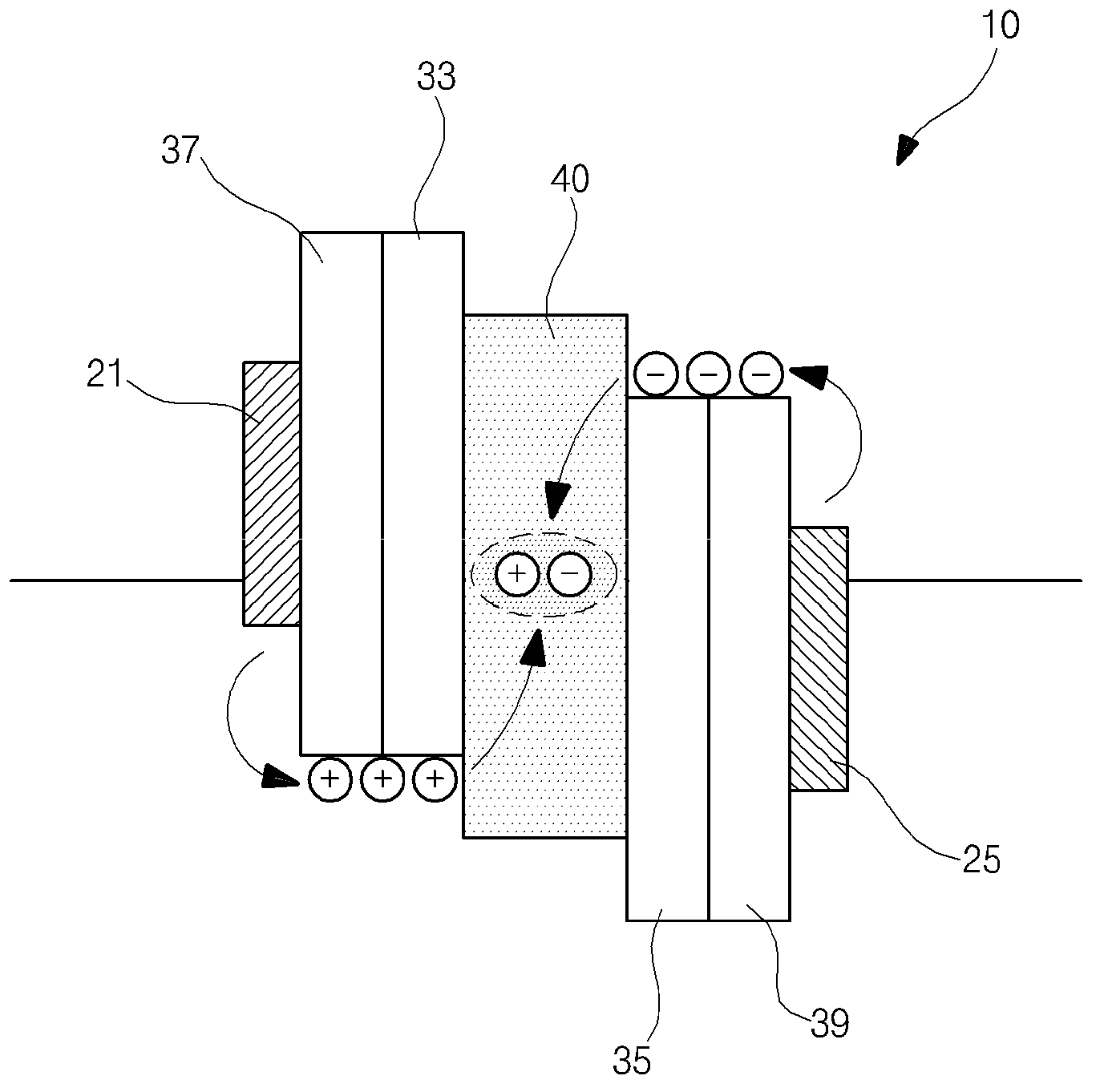
Therefore, the manufacturing time of the OLED display device 10 increases as the number of vacuum thermal evaporation operations increases
Also, since various emission colors of organic materials are required, material costs are increased and production efficiency is low

Method used


Image

  • Organic light emitting diode display device
  • Organic light emitting diode display device
  • Organic light emitting diode display device

Examples


no. 1 approach -

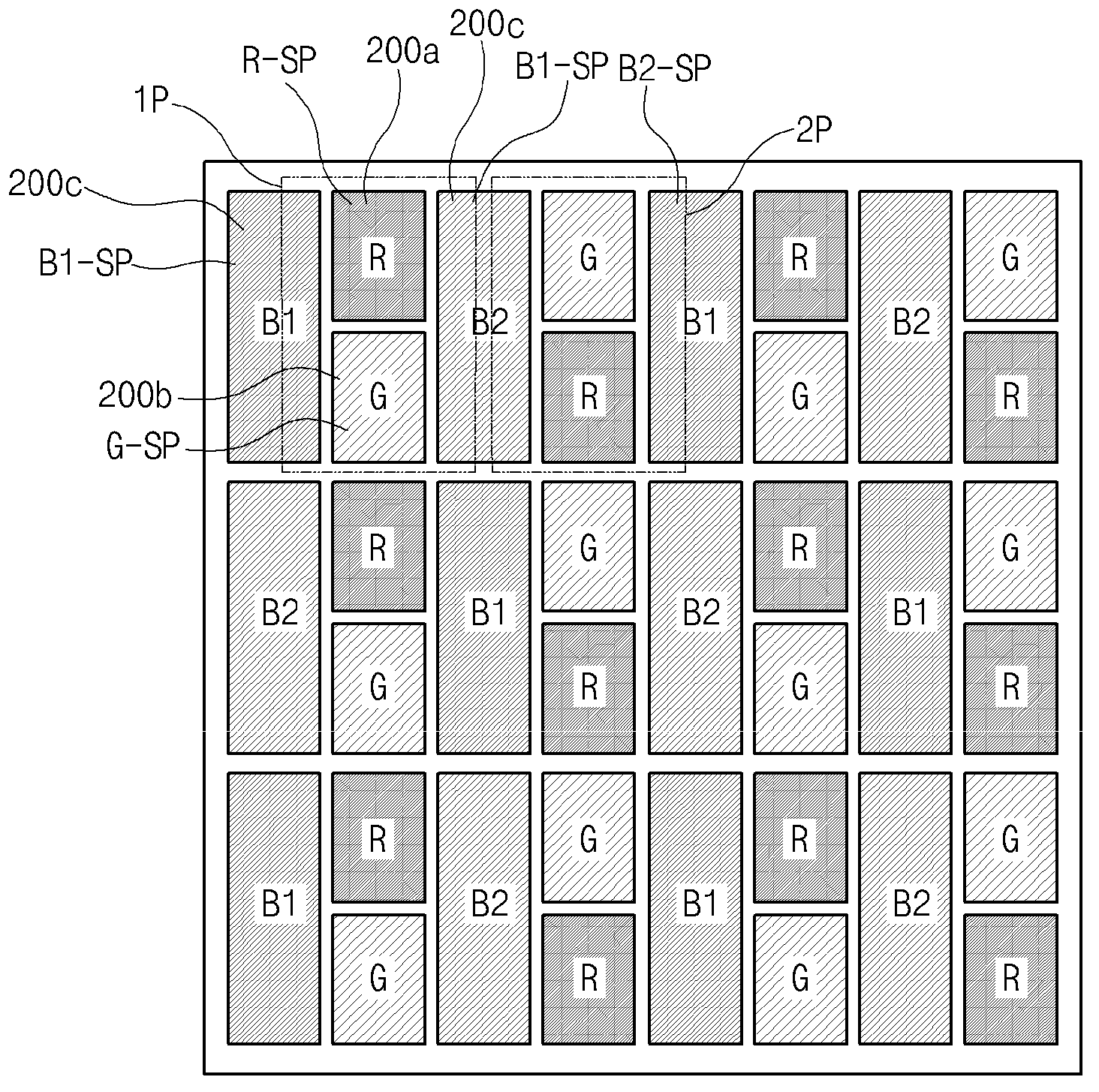
[0088] Figure 4 It schematically shows the red (R) sub-pixel R-SP, the green (G) sub-pixel G-SP, the deep blue (B1) sub-pixel B1-SP and the sky blue light according to the first embodiment of the present invention (B2) View of the cross-section of the OLED display device of sub-pixel B2-SP.

[0089] Such as Figure 4 As shown in , each of the R subpixel R-SP, the G subpixel G-SP, the B1 subpixel B1-SP, and the B2 subpixel B2-SP has a stacked structure including a first electrode 111, a hole Injection layer (HIL), hole transport layer (HTL), R luminescent material layer 200a, G luminescent material layer 200b, B1 luminescent material layer / B2 luminescent material layer 200c, electron transport layer (ETL), electron injection layer (EIL) and the second electrode 115.

[0090] The first electrode 111 has a double layer structure of a reflective layer 111a and a transparent layer 111b. The reflective layer 111 a may be formed of a metal such as aluminum (Al), tantalum (Ta), s...

no. 2 approach -

[0111] Image 6 is a view schematically showing a cross-section of an OLED display device of red (R), green (G), deep blue (B1 ) and sky blue (B2 ) sub-pixels according to the second embodiment of the present invention.

[0112] Such as Image 6 As shown in , each of the R subpixel R-SP, the G subpixel G-SP, the B1 subpixel B1-SP, and the B2 subpixel B2-SP has a stacked structure including a first electrode 111, a hole Injection layer (HIL), hole transport layer (HTL), R luminescent material layer 200a, G luminescent material layer 200b, B1 luminescent material layer / B2 luminescent material layer 300, electron transport layer (ETL), electron injection layer (EIL) and the second electrode 115.

[0113] The first electrode 111 has a double layer structure of a reflective layer 111a and a transparent layer 111b. The reflective layer 111 a may be formed of a metal such as aluminum (Al), tantalum (Ta), silver (Ag), or the like.

[0114] The transparent layer 111b may preferably...


PUM


Abstract

Provided is an organic light-emitting diode (OLED) display device having sub-pixels with four colors. When a B1 sub-pixel that represents deep blue and a B2 sub-pixel that represents sky blue are formed, by using a high efficiency blue organic material to form the same emission material layers in both the B1 and B2 sub-pixels such that a microcavity effect is implemented only in the B2 sub-pixel and a sky blue peak is extracted from the high efficiency blue organic material of the B2 sub-pixel, the emission material layer of the B2 sub-pixel represents sky blue. Therefore, a process of depositing emission material layers is simplified, which leads to a short process time and a reduction of the cost of materials, resulting in improvement in process efficiency of the OLED display device.

Description

technical field [0001] The present disclosure relates to an organic light emitting diode (OLED) display device, and more particularly, to an organic light emitting diode (OLED) display device having sub-pixels with four colors. Background technique [0002] For a long time, cathode ray tubes (CRTs) have been widely used as display devices. Recently, however, flat panel displays such as plasma display panels (PDP), liquid crystal displays (LCD), and organic light emitting diode (OLED) display devices have been developed as display devices capable of replacing CRTs and are widely used. [0003] Among flat panel displays, OLED display devices, which are self-emitting devices, can be manufactured as light-weight and thin products because they do not require a backlight, unlike LCDs, which are non-light-emitting devices. [0004] Also, the OLED display device is excellent in viewing angle and contrast, has advantages in power consumption, allows DC low voltage driving, and has a...

Claims


Application Information

Patent Timeline
Patent Type & Authority Applications(China)
IPC IPC(8): H01L27/32H10N10/856
CPCH01L27/32H01L27/3213H01L51/5265H10K59/351H10K59/805H10K59/876H10K50/11H10K50/30H10K50/852
Inventor 金龙哲柳俊锡
Owner LG DISPLAY CO LTD
Learn More