
Timing method and timing system

A time correction and time technology, applied in the field of clocks and watches, can solve the problems of correction time delay, data signal interference, affecting the correction effect, etc.

Inactive Publication Date: 2013-05-08
ZHUHAI PRECISION ELECTRONICS
View PDF6 Cites 9 Cited by
  • Summary
  • Abstract
  • Description
  • Claims
  • Application Information

AI Technical Summary

Problems solved by technology

[0003] For this reason, some manufacturers have developed and researched some technical methods and equipment for solving the above problems, but these methods and equipment need to repeatedly establish connections between the calibration equipment and the watch, and transmit data, which is prone to calibration time lag and The data signal is interfered during transmission, which seriously affects the correction effect, and even makes the clock equipment unable to complete the time correction, and consumes a lot of power

Method used


Image

  • Timing method and timing system
  • Timing method and timing system
  • Timing method and timing system

Examples


Embodiment Construction

[0023] The technical solution of the present invention will be described in detail below in conjunction with the accompanying drawings.

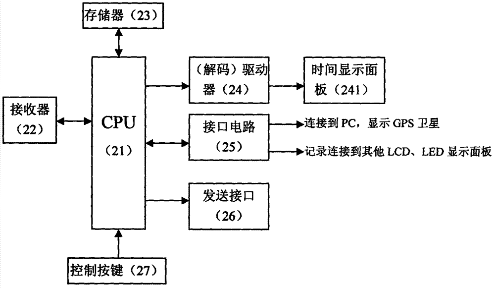
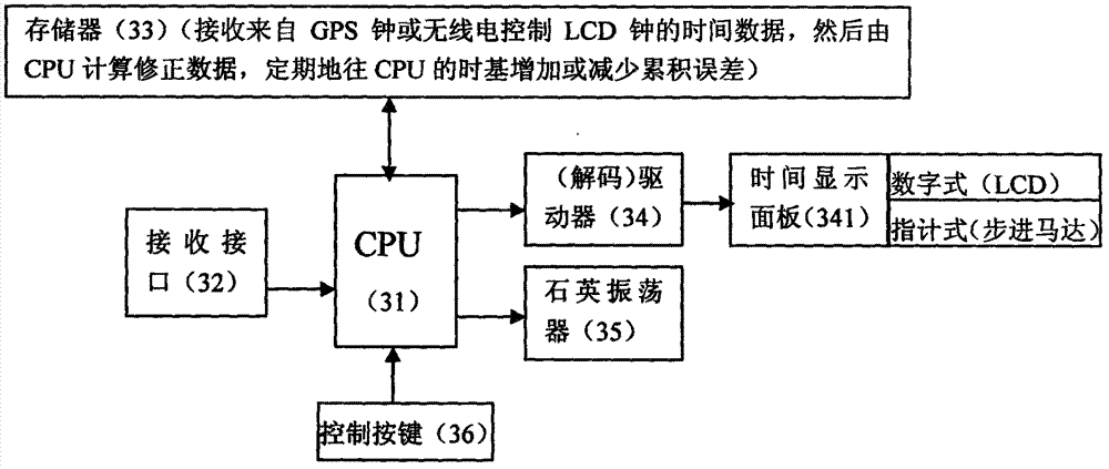
[0024] Please refer to the accompanying drawings Figure 1-5 . Among the figure, remote signal source 1, correction signal receiving equipment 2 (central processing unit 21, receiver 22, memory 23, driver 24, interface circuit 25, sending interface 26 and control button 27) and electronic timing device 3 (central processing unit 31 , receiving interface 32, memory 33, driver 34, quartz oscillator 35, control buttons 36, multi-stage frequency divider 37, multi-function controller 38, calibration interval timer 39 and automatic calibration circuit 30).

[0025] Such as figure 1 as shown in:

[0026] A time correction system according to the present invention includes a remote signal source 1, a correction signal receiving device 2 and an electronic timing device 3, wherein the remote signal source 1 is mainly used to provide a standard time...


PUM


Abstract

The invention provides a timing method. The timing method comprises the following steps: first, a correction signal receiving device sends a standard time signal to an electronic timing device; followingly, the electronic timing device calculates a new corrected value X1 according to the standard time signal; and eventually, the electronic timing device automatically corrects according to the new corrected value X1, and accomplishes correction. Namely, the annoyance when timing and time regulating by hands are needed regularly and the inconvenience brought about by serious inaccurate timekeeping can be reduced in a using process; and one-way connection is adopted for both the electronic timing device and the correction signal receiving device, only one time of connecting and standard time signal receiving is needed to accomplish time correction automatically, repeated connection and data transmission with the correction signal receiving device are not needed, correction time delay and transmission data signal interference are completely avoided, correction speed is quicker, and data are more accurate.

Description

【Technical field】 [0001] The invention belongs to the technical field of clocks and watches, and in particular relates to a time calibration method and a time calibration system. 【Background technique】 [0002] At present, due to the frequency error of the quartz crystal oscillator in the ordinary quartz watches on the market, at a normal temperature of 25°C, most of the monthly time difference of the clocks and watches is 20 seconds to 30 seconds or more; The monthly difference in travel time will be even greater. In order to correct the frequency error of the crystal oscillator and improve the timing accuracy of the watch, it is usually necessary to configure different capacitors for different crystal oscillators, which brings troubles to production. [0003] For this reason, some manufacturers have developed and researched some technical methods and equipment for solving the above problems, but these methods and equipment need to repeatedly establish connections between ...

Claims


Application Information

Patent Timeline
IPC IPC(8): G04R40/06
CPCG04G5/00G04R20/08
Inventor 陈笠黄世蔚彭保基
Owner ZHUHAI PRECISION ELECTRONICS
Learn More