
Uniaxial creep testing device and method for frozen earth with temperature gradient

A temperature gradient and creep test technology, applied in the direction of testing the ductility of materials, etc., can solve the problem that the mechanism and evolution law of the temperature gradient effect cannot be directly observed and extracted, the material unit test cannot cover the temperature gradient factor, and frozen soil engineering coupling There have been no breakthroughs and progress in the study of the mechanism of action, and the effect of flexible applicable pressure range, low cost, and improved temperature control accuracy has been achieved.

Active Publication Date: 2013-05-08
CHINA UNIV OF MINING & TECH
View PDF1 Cites 22 Cited by
  • Summary
  • Abstract
  • Description
  • Claims
  • Application Information

AI Technical Summary

Problems solved by technology

The uniform temperature frozen soil test block test belongs to the important factor that the material unit test cannot cover the temperature gradient factor. The model test belongs to the indoor scale test of the actual frozen soil engineering. Although it can reflect the actual temperature gradient factor and the characteristics of time and space distribution, it cannot directly Observation and extraction of the mechanism and evolution of the temperature gradient effect, so that the coupling mechanism of the temperature gradient factor and other engineering environmental variables (load properties, soil water content, temperature conditions, scale effects, etc.) on the stability of frozen soil engineering can be studied Delayed breakthroughs and progress

Method used


Image

  • Uniaxial creep testing device and method for frozen earth with temperature gradient

Examples


Embodiment Construction

[0019] An embodiment of the present invention will be further described below in conjunction with accompanying drawing:

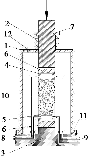
[0020] The temperature gradient frozen soil uniaxial creep test device of the present invention mainly consists of a pressure cover 1, a height adjustment cushion block 2, a convex base 3, an upper cooling plate 4, a lower cooling plate 5, an upper heat insulation plate 6-1, a lower insulation plate The hot plate 6-2 and the piston 7 are formed, the pressure cover 1 is screwed on the convex base 3, and the fixed contact surface between the pressure cover 1 and the convex base 3 is provided with a sealing ring. The pressure cover 1 is provided with an upper cooling plate 4 and a lower cooling plate 5 for fixing the sample 10, the lower cooling plate 5 is provided with a lower heat insulation plate 6-2 located on the boss in the middle of the convex base 3, and the upper cooling plate 4 is There is an upper heat shield 6-1, and the upper heat shield 6-1 is pr...


PUM


Abstract

The invention discloses a uniaxial creep testing device and a uniaxial creep testing method for frozen earth with a temperature gradient. The device consists of a pressure cover, a height adjusting cushion block, a convex pedestal, an upper refrigerating plate, a lower refrigerating plate and heat insulation plates, wherein a piston and a vacuumizing channel are arranged at the upper part of the pressure cover in a sliding way, and refrigerating fluid circulating channels and a test lead wire channel are formed in the convex pedestal. In the testing process, the heat insulation plate, the lower refrigerating plate, a sample, the upper refrigerating plate, the heat insulation plate and the pressure cover are sequentially mounted on the convex pedestal, and the space between the convex pedestal and the pressure cover is sealed by an O-shaped seal ring; an adiabatic boundary condition required by the sample is realized by vacuumizing in the pressure cover; the vertical temperature gradient of the sample is realized by regulating cold medium temperatures in the upper refrigerating plate and the lower refrigerating plate; and a creep load required by the sample is realized by regulating the forced direction and size of the piston. According to the uniaxial creep testing device and the uniaxial creep testing method, a unidirectional stress state and the stable adiabatic boundary condition can be provided, and the device and the method are suitable for research of uniaxial creep characteristics of the frozen earth under the conditions of different temperature gradients and scales.

Description

technical field [0001] The invention relates to a geotechnical test device and method, in particular to a frozen soil uniaxial creep test device and method with a temperature gradient. Background technique [0002] Permafrost is a temperature-sensitive material, and mastering the influence of temperature on the deformation strength of permafrost has important reference value and scientific significance for the design and stability evaluation of buildings / structures on permafrost foundations. Whether it is natural frozen soil (such as seasonal frozen soil in Northeast China, permafrost in Qinghai-Tibet Plateau) or artificial frozen soil (such as artificially frozen extra-thick topsoil and water-bearing soft rock in East China and Mongolia-Shanxi region), it is affected by formation temperature, atmospheric Due to the combined effects of temperature, refrigerant temperature, exposure time and good environmental conditions, the temperature field of the permafrost medium is a ty...

Claims


Application Information

Patent Timeline
IPC IPC(8): G01N3/28
Inventor 赵晓东周国庆鲍强阴琪翔李瑞林陈阳光
Owner CHINA UNIV OF MINING & TECH
Learn More