Light-diffusing film laminate
A technology of light diffusing films and laminates, applied in optics, optical elements, nonlinear optics, etc., can solve the problems of improving the brightness of components, and achieve the effects of high brightness, performance improvement, and uniformity improvement.
- Summary
- Abstract
- Description
- Claims
- Application Information
AI Technical Summary
Problems solved by technology
Method used
Image

Examples
Embodiment
[0285] Hereinafter, examples are given to describe the present invention more specifically, but the present invention is not limited by the following examples, and can also be appropriately modified and implemented within the scope of the gist of the present invention, and these are included in the technical scope of the present invention. In addition, the measurement and evaluation methods used in the Examples are as follows. In addition, in the examples, "parts" means "parts by mass" unless otherwise stated, and "%" means "mass%" unless otherwise stated.
[0286] 1. Total light transmittance
[0287] A device with an integrating sphere (ISR-3100; manufactured by Shimadzu Corporation) was installed in a self-recording spectrophotometer (UV-3150; manufactured by Shimadzu Corporation), and a wavelength of 300 to 800 nm was scanned at high speed with a slit width of 12 nm. range, spectroscopic measurement is performed, expressed as the transmittance at 550nm.
[0288] In this ...
manufacture example 1
[0349] Using two melt extruders, 35 parts by mass of a cyclic polyolefin resin (TOPAS(TM) 6013S-04 manufactured by Topas Advanced Polymers, melt flow rate: 2.0 (230° C.)) was mixed with ethylene and 65 parts by mass of block copolymer resin (INFUSE(TM) D9817.15 manufactured by Dow Chemical Co., Ltd., melt flow rate: 26 (230° C.)) formed of octene was used to form a light diffusion layer, and the second extruder was used. After making the polypropylene adhesive resin (Adomer(TM) SE800, manufactured by Mitsui Chemicals Co., Ltd., melt flow rate: 5.7 (190° C.)) two surface layers, melt and co-extrude it with a T-die, and then use The internal light-diffusion film which laminated|stacked the heat-adhesive layer on both surfaces with a total thickness of 400 micrometers was obtained by cooling with a mirror-surface cooling roll. Adhesion between the film and the cooling roll during the above-mentioned cooling is performed using a vacuum chamber. The layer thickness composition was...
manufacture example 2
[0352]Cyclic polyolefin-based resin (TOPAS (TM) 6015 manufactured by Topas Advanced Polymers, melt flow rate: 0.41 (230° C.)) 50 parts by mass and block copolymer resin composed of ethylene and octene (INFUSE manufactured by Dow Chemical Company ( TM) D9817.15 melt flow rate: 26 (2300)) 50 parts by mass, melted and mixed with the extruder PCM45 manufactured by Ikegai Iron Works Co., Ltd. at a resin temperature of 250° C., extruded with a T-shaped die, and used The textured cooling roll (Ra=0.55) cooled to obtain an inner light-diffusing film having a thickness of 400 μm. In addition, the surface opposite to the said cooling roll used the squeeze roll which performed the mold release process (Ra=1.0) on the surface.
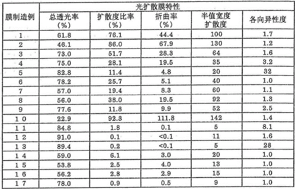
[0353] Table 1 shows the properties of the obtained inner light-diffusing film.
PUM
 Abstract
Description
Claims
Application Information
 - R&D
- Intellectual Property
- Life Sciences
- Materials
- Tech Scout
- Unparalleled Data Quality
- Higher Quality Content
- 60% Fewer Hallucinations
Browse by: Latest US Patents, China's latest patents, Technical Efficacy Thesaurus, Application Domain, Technology Topic, Popular Technical Reports.
© 2025 PatSnap. All rights reserved.Legal|Privacy policy|Modern Slavery Act Transparency Statement|Sitemap|About US| Contact US: help@patsnap.com