Projection light source and projection device using same

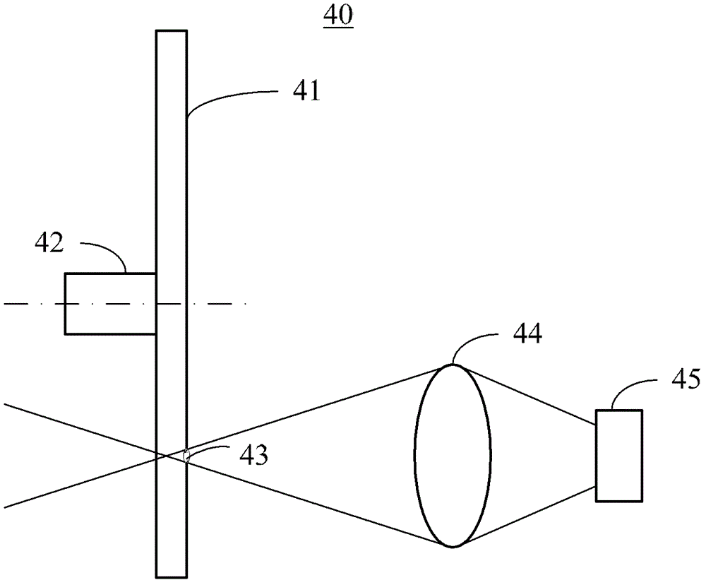
A projection and light source technology, applied in the field of projection, can solve the problems such as the decrease of output light efficiency of projection light source 40, the change of radiation wavelength, and the acceleration of phosphor powder, so as to achieve the effects of improving output light efficiency, increasing fluorescence efficiency, and reducing duty cycle

Active Publication Date: 2015-05-27
APPOTRONICS CORP LTD
View PDF9 Cites 0 Cited by
  • Summary
  • Abstract
  • Description
  • Claims
  • Application Information

AI Technical Summary

Problems solved by technology

Studies have shown that as the temperature rises, the quantum efficiency of the phosphor will decrease, resulting in a decrease in the emitted light of the phosphor, and a change in the wavelength of the radiation, which will cause changes in color temperature and chromaticity; on the other hand, higher temperatures will also accelerate Phosphor Aging
[0008] However, in the prior art, the excitation light emitted by the laser light source 45 usually converges on the fluorescent pink wheel 41 in the form of spot spots, which will form very strong light radiation on the color wheel area where the spot 43 is located, resulting in a higher temperature. , will reduce the luminous efficiency and conversion efficiency of the phosphor, and then reduce the output light efficiency of the projection light source 40, and the color temperature and chromaticity of the output light beam will change, resulting in poor image display effect of the projector.

Method used


Image

  • Projection light source and projection device using same
  • Projection light source and projection device using same
  • Projection light source and projection device using same

Examples


Embodiment Construction

[0023] The present invention will be further described in detail below in conjunction with the accompanying drawings.

[0024] In order to make it easier for those skilled in the art to understand the technical solution of the present invention, the structure and working principle of the projection device of the present invention will be described first.

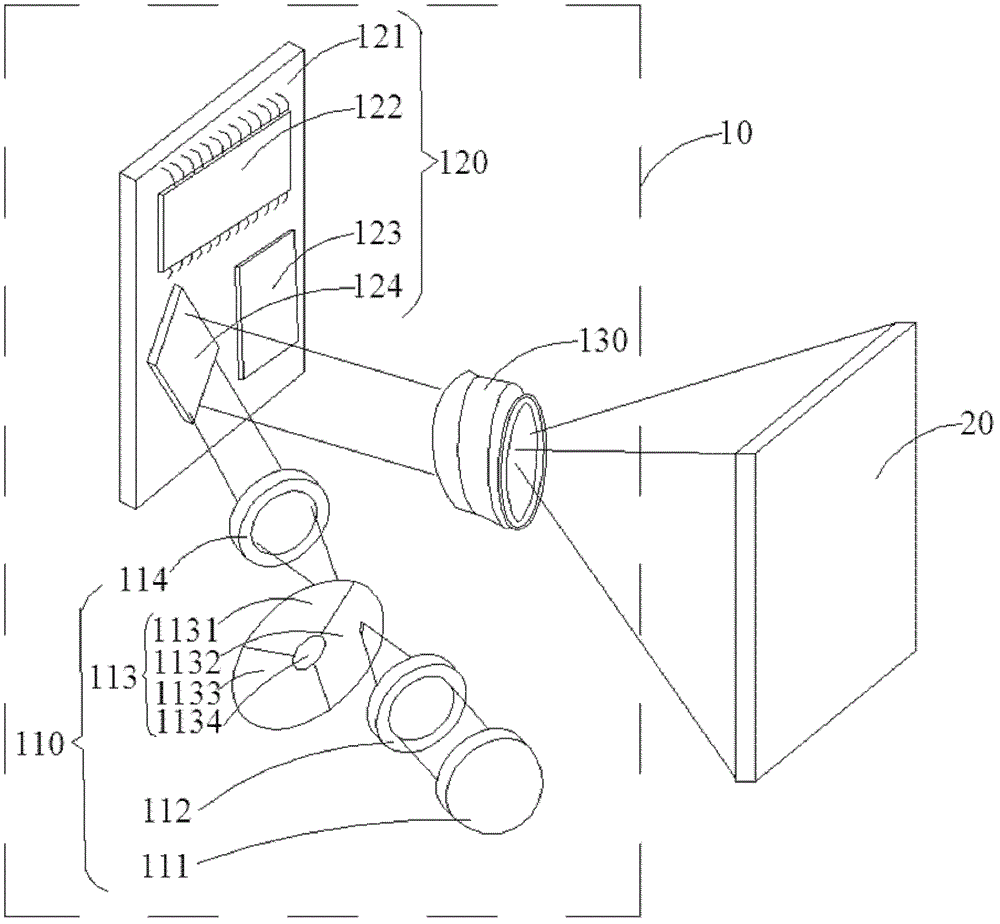
[0025] figure 2 It is a structural schematic diagram of a preferred embodiment of the projection device of the present invention. Such as figure 2 As shown, the projection device 10 of the present invention mainly includes a projection light source 110 , a digital optical processing unit 120 and a projection lens 130 . The projection light source 110 is used to generate a periodic and time-sequential color light sequence, and project the color light sequence to the digital optical processing unit 120 . The digital optical processing unit 120 receives a digital or analog image signal, processes the image signal into a sw...


PUM


Abstract

The invention provides a projection light source and a projection device. The projection light source comprises a light source and a color wheel. The light source is used for generating exciting light. The color wheel faces the light source, rotates around a rotating shaft, and comprises a plurality of optical wavelength conversion regions which are arranged on a propagation path of the exciting light source to receive the exciting light and to convert the exciting light into fluorescence corresponding to the optical wavelength conversion regions. The fluorescence generates a colored light sequence of a periodic time sequence along with the rotation of the color wheel. The exciting light generated by the light source forms light spots on the color wheel, and the projection sizes of the light spots in the direction of motion of the color wheel are larger than those of the light spots in at least another direction of the color wheel. According to the projection light source, the position and the direction of the exciting light projected onto the color wheel are regulated, so that the fluorescence efficiency of the color wheel can be improved, the temperature of a light spot region on the color wheel can be reduced, the efficiency of output light of the projection light source can be improved, and the stability of the color temperature and the chromaticity of output light beams can be maintained.

Description

technical field [0001] The invention relates to the field of projection technology, in particular to a projection light source using a fluorescent pink wheel and a projection device using the projection light source. Background technique [0002] As computer peripherals are gradually becoming mobile, projector equipment is also developing towards lightweight, which has given birth to miniature projectors. The pico projector is mainly integrated with mobile devices, embedded in mobile phones, digital cameras, tablet computers and other devices, and powered by the battery of the mobile device, so that it can be carried around in a true sense. [0003] At present, the UHP (Ultra High Power) light source commonly used in ordinary projectors cannot be applied to micro-projectors due to reasons such as size, power consumption, and heat dissipation. Therefore, it is necessary to develop a micro-projection light source to cooperate with it. [0004] Compared with traditional UHP li...

Claims


Application Information

Patent Timeline
Patent Type & Authority Patents(China)
IPC IPC(8): G03B21/20G02B7/00G03B21/14G03B21/00F21V14/08
CPCG02B26/008G03B21/204G03B21/208
Inventor 杨毅
Owner APPOTRONICS CORP LTD
Why Eureka
Try Eureka