
Parallel flow evaporator

An evaporator and parallel flow technology, which is applied in the direction of evaporator/condenser, heat exchanger shell, heat exchange equipment, etc., can solve the problems of not being able to guarantee the same flow rate into each pipeline and affecting the heat exchange effect, and achieve reduction Dissipation of energy, uniform flow, and the effect of reducing product cost

Inactive Publication Date: 2013-05-01
TIANJIN DARK HORSE IND & TRADE CO LTD
View PDF5 Cites 0 Cited by
  • Summary
  • Abstract
  • Description
  • Claims
  • Application Information

AI Technical Summary

Problems solved by technology

At present, the liquid collection pipes of parallel flow evaporators use long round pipes or long flat pipes to divide the flow, which cannot guarantee the same flow rate into each pipe, which affects the heat exchange effect

Method used


Image

  • Parallel flow evaporator
  • Parallel flow evaporator

Examples


Embodiment Construction

[0016] The present invention will be described in further detail below in conjunction with the accompanying drawings and specific embodiments.

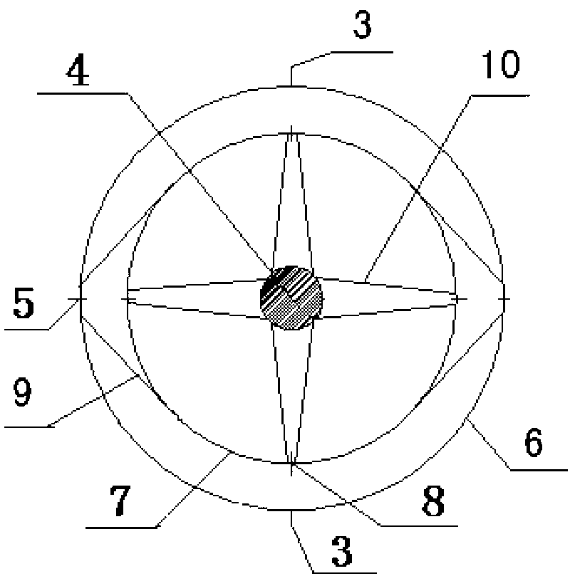
[0017] The schematic diagram of parallel flow evaporator of the present invention is as figure 1 , figure 2 As shown, it includes a liquid distributor 4, an inner circular evaporation tube 7, an outer circular evaporation tube 6, a plurality of first evaporation tubes 10, and a plurality of second evaporation tubes 9. The liquid distributor 4 is disc-shaped, The disk-shaped center of the liquid distributor 4 is provided with a liquid inlet, and the disk-shaped edge of the liquid distributor 4 is provided with a plurality of symmetrical liquid outlets. The liquid inlet of the liquid distributor 4 A liquid inlet pipe 2 is installed on the mouth, and each of the first evaporation pipes 10 is connected between the liquid outlet of the liquid distributor 4 and the liquid inlet on the inner circular evaporation pipe 7. The second evapora...


PUM


Abstract

The invention discloses a parallel flow evaporator, aiming at providing an evaporator which is capable of realizing balanced flow, and is good in heat exchange effect and low in cost. A liquid distributor is in a disc shape; a liquid inlet is arranged in the center of the disc shape of the liquid distributor; a plurality of symmetrical liquid outlets are arranged at the disc-shaped edge; a liquid inlet pipe is arranged at the liquid inlet of the liquid distributor; each first evaporating pipe is connected between each liquid outlet of the liquid distributor and a liquid inlet of an internal circular evaporating pipe; a plurality of second evaporating pipes are connected between the internal circular evaporating pipe and an external circular evaporating pipe; the internal circular evaporating pipe is symmetrically provided with a plurality of first baffles; due to the arrangement of the first baffles, the flow paths of all evaporation sections of the internal circular evaporating pipe are the same as one another; the external circular evaporating pipe is symmetrically provided with a plurality of second baffles; due to the arrangement of the second baffles, the flow paths of all evaporation sections of the external circular evaporating pipe are the same as one another; and a gas collecting pipe is arranged on the external circular evaporating pipe. The liquid in the evaporating pipes of the parallel flow evaporator is even in flow rate, so that the heat exchange effect is good.

Description

technical field [0001] The invention relates to the technical field of refrigeration, in particular to a parallel flow evaporator. Background technique [0002] After the liquid enters the evaporator, it needs to enter the evaporator tube quickly and evenly. However, due to the different positions of the tubes, the pressure drop is different, resulting in different flow rates of the liquid entering each tube, resulting in unbalanced heat transfer. , resulting in energy dissipation. [0003] In order to solve the above problems, a parallel flow evaporator has been developed. At present, the liquid collection pipes of parallel flow evaporators are divided by long round pipes or long flat pipes, which cannot guarantee the same flow rate into each pipe, which affects the heat exchange effect. Contents of the invention [0004] The object of the present invention is to provide an evaporator capable of achieving flow balance and good heat exchange effect in view of the technic...

Claims


Application Information

Patent Timeline
Patent Type & Authority Applications(China)
IPC IPC(8): F25B39/02F28F9/22
Inventor 刘斌申志远
Owner TIANJIN DARK HORSE IND & TRADE CO LTD
Learn More