Luminaire mounting mechanism and recessed luminaire including the mechanism

A lamp installation and mounting board technology, which is applied to the components of lighting devices, lighting devices, fixed lighting devices, etc., can solve the problems of poor adaptability of mounting holes, weakened elasticity and falling off of shrapnel devices, and achieve long service life and wide application range The effect of wide and strong support strength

Active Publication Date: 2015-10-28
广东美菲照明有限公司
View PDF5 Cites 0 Cited by
  • Summary
  • Abstract
  • Description
  • Claims
  • Application Information

AI Technical Summary

Problems solved by technology

There are mainly the following problems when using the shrapnel device to fix the lamps: first, the loading and unloading process is cumbersome, especially when the lamp is unloaded, it is easy to damage the ceiling; second, the support strength is unstable. The elasticity of the shrapnel device will gradually weaken, causing the lamp to sag or even fall off; third, the adaptability to the installation hole is poor. When installing the lamp, a certain gap must be left for the shrapnel device to pass through, but if the installation hole is opened too much, it will cause clamping. Insufficient, not fit the lamp surface and other problems, the installation hole is too small, it is difficult to insert the lamp into the installation hole during installation

Method used


Image

  • Luminaire mounting mechanism and recessed luminaire including the mechanism
  • Luminaire mounting mechanism and recessed luminaire including the mechanism
  • Luminaire mounting mechanism and recessed luminaire including the mechanism

Examples


Embodiment Construction

[0020] The present invention will be further described below through specific embodiments.

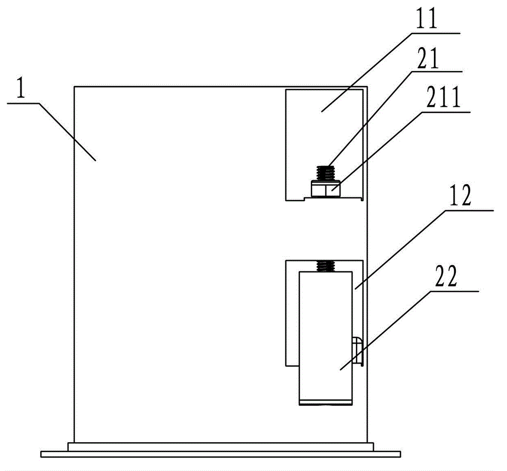
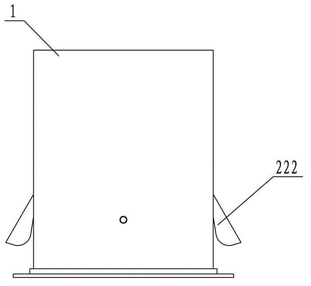
[0021] refer to Figure 1 to Figure 6 As shown, a lamp installation mechanism includes a lampshade 1 and a clamping device 2 installed on the lampshade 1 .

[0022] The left and right sides of the lampshade 1 are respectively provided with vertically arranged upper through holes 11 and lower through holes 12, and the lower edges of the upper through holes 11 and the lower through holes 12 are respectively formed with an upper mounting plate 13 extending inwardly. and the lower mounting plate 14, and the upper mounting plate 13 and the lower mounting plate 14 have mounting holes respectively. The clamping device 2 includes a screw rod 21, a supporting part 22, a transmission shaft 23, and a stopper 24. The screw rod 21 is vertically installed in the lampshade 1, and the supporting part 22 is injection-molded at one time. One end is a connecting part 221, and the other end is a supporti...


PUM


Abstract

The invention relates to the technical field of illumination, in particular to a lamp installation mechanism and an embedded lamp comprising the same. The lamp installation mechanism comprises a bracket and a clamping device installed on the bracket, wherein the bracket is provided with a through hole; the clamping device comprises a screw, a support component and a transmission shaft; the screw is vertically installed on the inner side of the bracket; one end of the support component is connected with the screw by the transmission shaft to form a connection part capable of radially rotating around the screw; the other end of the support component extends out of the through hole along with the rotation of the connection part to form a support component ; the transmission shaft is horizontally arranged on the connection part and is provided with a screw hole adaptive to the thread of the screw; the screw passes through the screw hole in the transmission shaft to be fixedly arranged on the bracket; and the opening and the closing of the support component can be regulated by rotating the screw. The embedded lamp comprises a light source, a surface cover and the lamp installation mechanism. The lamp installation mechanism and the embedded lamp have the advantages of convenience in installing and disassembling, firmness in supporting, and strong adaptability to an installation hole, and different installation requirements can be satisfied.

Description

technical field [0001] The invention relates to the field of lighting technology, in particular to a lamp installation mechanism and an embedded lamp including the mechanism. Background technique [0002] At present, the embedded installation of the lamp is mainly completed through the shrapnel device, and the two ends of the shrapnel device are respectively the installation end connected with the lamp and the clamping end forming a certain angle with the installation end. When installing, first put away the clamping end of the shrapnel device, insert the lamp together with the shrapnel device into the installation hole of the ceiling, the shrapnel device produces elastic deformation in the installation hole, and the clamping end opens to support the lamp on the ceiling. There are mainly the following problems when using the shrapnel device to fix the lamps: first, the loading and unloading process is cumbersome, especially when the lamp is unloaded, it is easy to damage the...

Claims


Application Information

Patent Timeline
Patent Type & Authority Patents(China)
IPC IPC(8): F21V21/02F21S8/02F21Y101/02
Inventor 曾志宏
Owner 广东美菲照明有限公司
Why Eureka
Try Eureka