Eureka AIR delivers breakthrough ideas for toughest innovation challenges, trusted by R&D personnel around the world.

Two-wheel-driven bidirectional heavy-pipe deep stirring ground wall connecting machine

A technology of deep stirring and wall machine, applied in the direction of drill pipe, casing, sheet pile wall, etc., can solve the problems such as the cement content of the wall does not reach the due index, the drill pipe is slurried, and the quality of the wall is affected. Eliminate pulp phenomenon, ensure verticality, and ensure the effect of quality

Inactive Publication Date: 2013-05-01
JIANGSU XINGSHA CONSTR ENG GRP
View PDF10 Cites 3 Cited by
  • Summary
  • Abstract
  • Description
  • Claims
  • Application Information

AI Technical Summary

Problems solved by technology

[0006] 1. Uneven mixing of cement and soil is common, which affects the quality of the wall and has poor anti-seepage effect;
[0007] 2. It is common that the distribution of cement slurry in the wall is uneven, and there are more up and down than down, especially when it is below 7m.
[0008] 3. During the construction process, there is a common phenomenon of mud escaping along the periphery of the drill pipe, and the mud emerges from the surface, causing the cement content in the wall to fall short of the expected target.
[0009] 4. At present, the mechanical construction technology is generally four stirring and four spraying, and the work efficiency is low.

Method used


Image

  • Two-wheel-driven bidirectional heavy-pipe deep stirring ground wall connecting machine
  • Two-wheel-driven bidirectional heavy-pipe deep stirring ground wall connecting machine
  • Two-wheel-driven bidirectional heavy-pipe deep stirring ground wall connecting machine

Examples


Embodiment Construction

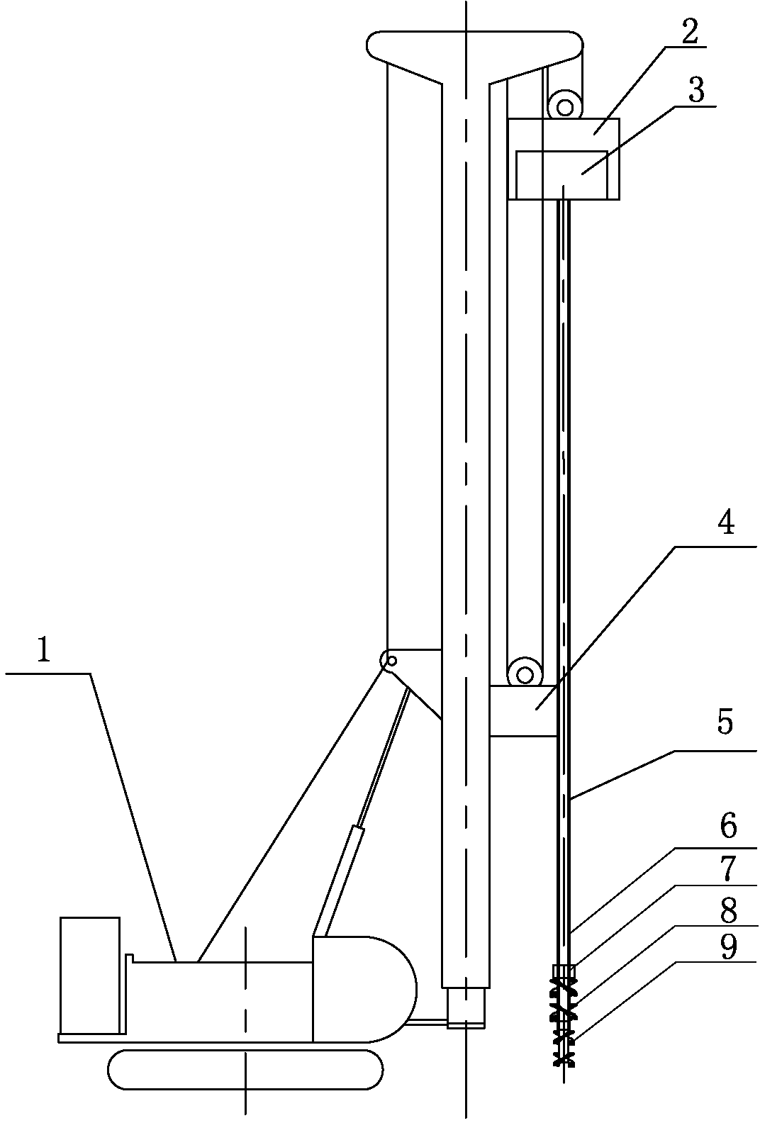
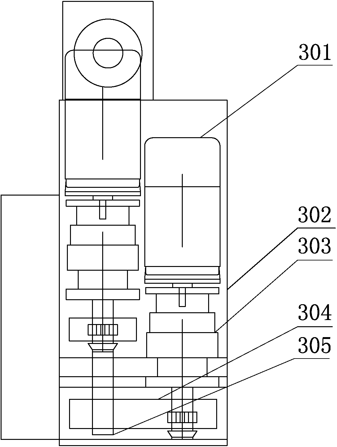
[0029] Such as figure 1 — Figure 5 Shown is the two-drive two-way heavy-pipe deep-stirring ground-wall connecting machine of the present invention, including drill pipes. In this embodiment, the drill pipes are 5 groups arranged parallel to each other. The lower parts of each drill pipe respectively pass through the cage 7, and the drill pipes The top is provided with a lifting platform 2, and the drill rods include a hollow inner drilling rod 6 and an outer drilling rod 5 which are arranged concentrically and can rotate in opposite directions. The inner drilling rod 6 and the outer drilling rod 5 are rotatably connected below the lifting platform 2, and the lifting platform 2 is provided with a top drive mechanism 3 for driving the rotation of the inner drill rod 6, and the lifting table 2 is suspended on the support machine 1 through a wire rope; the middle part of the outer drill rod 5 is provided with a middle drive mechanism 4 for driving the rotation of the outer drill...


PUM


Abstract

The invention relates to a two-wheel-driven bidirectional heavy-pipe deep stirring ground wall connecting machine for building an anti-seepage underground continuous wall in the field of engineering drillers. The two-wheel-driven bidirectional heavy-pipe deep stirring ground wall connecting machine comprises drill rods, wherein an elevating table is arranged on the tops of the drill rods; the drill rods include hollow inner drill rods and hollow outer drill rods which are arranged concentrically and can rotate towards each other; the inner drill rods and the outer drill rods are rotationally connected below the elevating table; the elevating table is provided with a top driving mechanism for driving the inner drill rods to rotate; the elevating table is suspended on a supporting machine through a steel wire rope; the middle parts of the outer drill rods are provided with a middle driving mechanism for driving the outer drill rods to rotate; the inner drill rods extend out of the lower ends of the outer drill rods; the peripheries of the extension ends of the inner drill rods are provided with lower stirring blades; and the lower ends of the outer drill rods are provided with upper stirring blades rotating opposite to the lower stirring blades. According to the two-wheel-driven bidirectional heavy-pipe deep stirring ground wall connecting machine, stirring uniformity, a good anti-seepage effect and high production efficiency are realized, and cement grout is effectively prevented from spilling over along the drill rods.

Description

technical field [0001] The invention relates to an engineering drilling rig, in particular to a single-head or multi-head deep digging and connecting wall machine for building an anti-seepage underground continuous wall on a permeable foundation. Background technique [0002] The cement-soil mixing pile was successfully developed by the United States after World War II, and it is called a mixing-in-place pile (MIP). The in-situ mixing pile sprays cement slurry from the end of the continuously rotating vacuum shaft to the surrounding soil that has been stirred, and is stirred by blades to form a cement-soil pile with a pile diameter of 0.3~0.4m and a length of 10~12m. In 1953, Japan Shimizu Construction Co., Ltd. introduced this method from the United States. In 1967, the Geotechnical Department of Japan Harbor Technology Research Institute began to develop lime mixing construction machinery. In 1974, the Japanese Port Technology Research Institute and other units successful...

Claims


Application Information

Patent Timeline
IPC IPC(8): E02D5/18E02D5/46E21B3/02E21B17/00E21B17/22
Inventor 孙刚陈福坤李大进刘利花薛玉文徐春荣钱冬冬吴德源
Owner JIANGSU XINGSHA CONSTR ENG GRP
Why Eureka
Eureka Blog
Learn More