
Front-mounted hydraulic cylinder lifting mechanism for light and medium-duty dump trucks

A technology of lifting mechanism and dump truck, which is applied in the direction of inclined load-carrying vehicles, etc. It can solve the problems of installation accessories and large installation space, high strength requirements of the lifting mechanism, and affecting the service life of the oil cylinder, so as to shorten the loading time , Ensure safety and stability, and improve work efficiency

Active Publication Date: 2015-12-30
CNHTC CHENGDU WANGPAI COMML VEHICLE
View PDF6 Cites 0 Cited by
  • Summary
  • Abstract
  • Description
  • Claims
  • Application Information

AI Technical Summary

Problems solved by technology

[0003] There are many shortcomings in the above structures: 1. The double-cylinder lifting mechanism has a high lifting center of gravity, a large lifting force, and a high requirement for the strength of the lifting mechanism; the installation accessories and installation space are large, and the manufacturing cost is relatively high. During the actual use of the double-cylinder lifting mechanism, there is often a certain difference in the frictional resistance of the two cylinders, and the change of the oil circuit system, and the expansion and contraction speed also has a certain difference, resulting in uneven force on the cylinder and affecting the service life of the cylinder.
2. The installation form of the tripod lifting mechanism and the double-cylinder lifting mechanism are basically the same, but it adopts the single-cylinder lifting principle, and the installation accessories are much larger than the double-cylinder lifting mechanism, and its manufacturing cost is correspondingly larger

Method used


Image

  • Front-mounted hydraulic cylinder lifting mechanism for light and medium-duty dump trucks

Examples


Embodiment 1

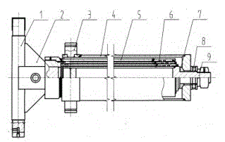
[0012] Example 1, such as figure 1 As shown, the purpose of the present invention is achieved through the following technical solutions. The present invention includes an outer protective cylinder 4, an outer cylinder 5, a movable ball joint 7, a piston rod 9, and an outer cylinder is provided with an oil inlet hole and a seal , which is characterized in that: it is also provided with a lower installation shaft 1, an upper installation shaft 3, a dirt receiving ring 6, and a reinforcement plate 2, the two ends of the lower installation shaft are connected with the frame, the middle part of the lower installation shaft is welded with a reinforcement plate, and the lower installation shaft is connected to the vehicle frame. The outer cylinder body is fastened and connected by threads, the upper mounting shaft is welded to the outer protective cylinder body, the two shaft ends of the upper mounting shaft are connected to the cargo box of the car, the movable ball hinge is installe...


PUM


Abstract

The invention discloses a roof-mounted type hydraulic cylinder lifting mechanism for a damper of a light and medium truck. The mechanism comprises an outer protective cylinder body (4), an outer cylinder body (5), a moveable spherical hinge (7) and a piston rod (9), wherein an oil inlet and a sealing member are arranged on the outer cylinder body. The mechanism is characterized by further comprising a lower installation shaft (1), an upper installation shaft (3), a dirt receiving ring (6) and a reinforcing plate (2). Both ends of the lower installation shaft are connected with a frame, the reinforcing plate is welded in the middle of the lower installation shaft, the lower installation shaft is in fastened connection with the outer cylinder body through a screw thread, the upper installation shaft is welded with the outer protective cylinder body, both shaft ends of the upper installation shaft are connected with an automobile container, the moveable spherical hinge is welded on the upper part of the piston rod, the outer protective cylinder body is sleeved on the moveable spherical hinge, and the top of the piston rod is sleeved with a shock absorbing gasket and is fixed by a locking nut. According to the invention, the oil cylinder is automatically leveled in the using process and still maintained vertical to the automobile body, so that, the quality product is greatly improved, and the safety and the stability of the product are ensured.

Description

technical field [0001] The invention relates to the field of hydraulic technology, in particular to a front-mounted hydraulic cylinder lifting mechanism for light and medium truck dump trucks. Background technique [0002] The hydraulic lifting mechanism is mainly used in the hydraulic lifting system of dump trucks, and is an indispensable actuator for automatic unloading. Its function is to input the hydraulic oil into the oil cylinder through the hydraulic oil pump, so that the oil cylinder extends under the action of the hydraulic oil. The oil cylinder is installed on the car cargo box and the frame, and the oil cylinder stretches out to drive the cargo box to a certain height. So as to achieve the effect of automatic unloading. At present, there are mainly two installation methods for the lifting mechanism of light and medium truck dump trucks commonly used in China: 1. Double-cylinder lifting mechanism (middle top); 2. Tripod lifting mechanism (middle top). [0003] T...

Claims


Application Information

Patent Timeline
Patent Type & Authority Patents(China)
IPC IPC(8): B60P1/16
Inventor 曹守国张凡勇赵志强张敏唐海宏
Owner CNHTC CHENGDU WANGPAI COMML VEHICLE
Learn More