
Downhole Liquid Sand Multistage Separator

A technology of separators and grit holes, applied in the direction of boreholes/well components, production fluids, settling tanks, etc., can solve problems such as clogged liquid inlet holes and separators that cannot work normally, and achieve the effect of ensuring normal operation

Active Publication Date: 2016-01-20
PETROCHINA CO LTD +1
View PDF3 Cites 1 Cited by
  • Summary
  • Abstract
  • Description
  • Claims
  • Application Information

AI Technical Summary

Problems solved by technology

[0003] The purpose of the present invention is to provide a multi-stage separator for downhole liquid sand, which can solve the problem that the existing oil-water separator blocks the liquid inlet hole due to sedimentation and sand deposition, and then makes the separator unable to work normally.

Method used


Image

  • Downhole Liquid Sand Multistage Separator
  • Downhole Liquid Sand Multistage Separator
  • Downhole Liquid Sand Multistage Separator

Examples


Embodiment Construction

[0014] Below in conjunction with accompanying drawing, the present invention will be further described:

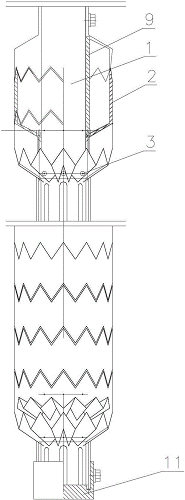
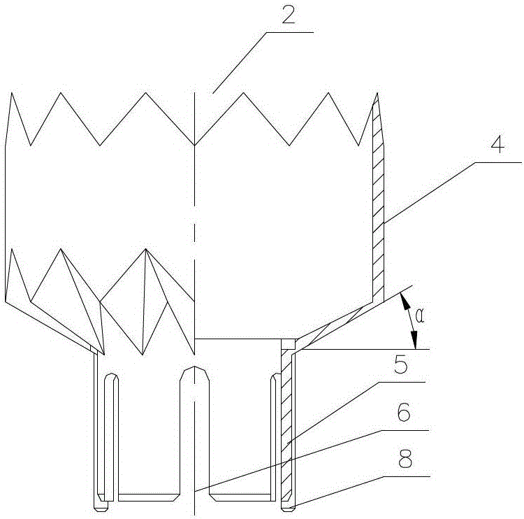
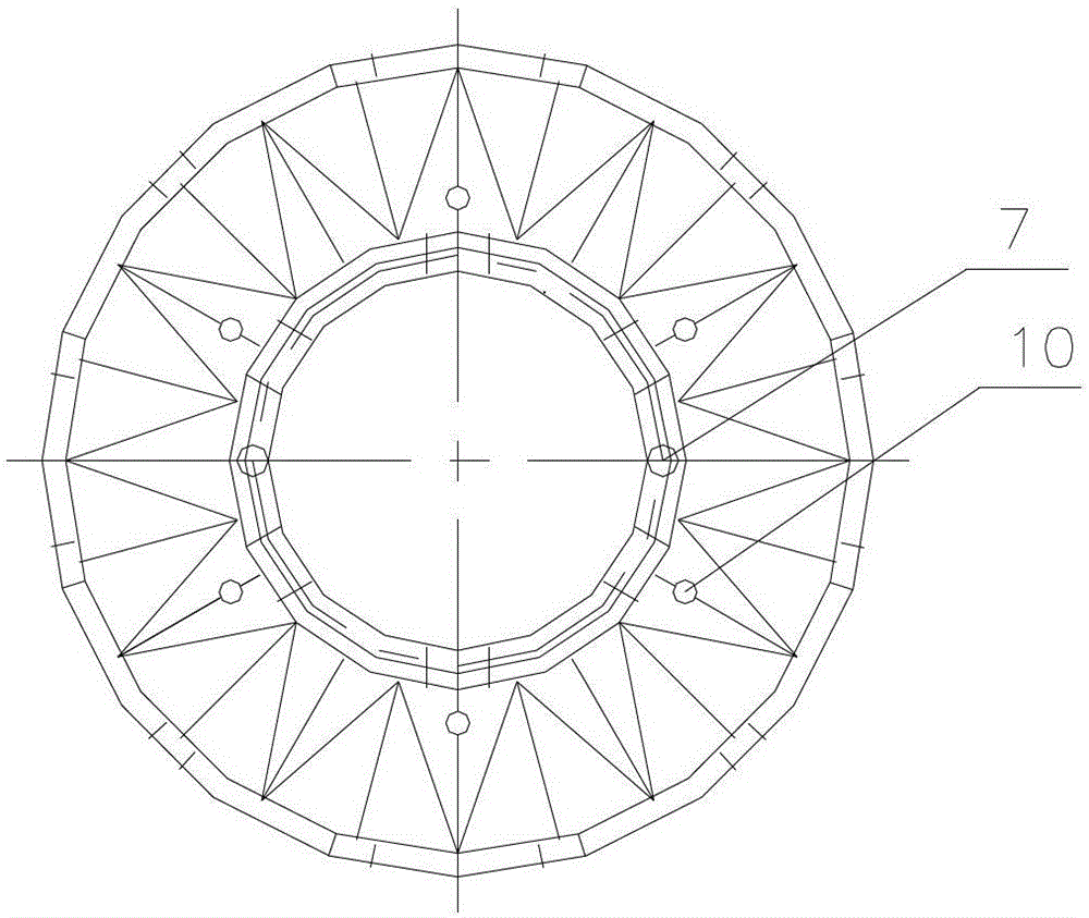
[0015] Depend on figure 1 combine figure 2 , 3 Shown: the downhole fluid-sand multi-stage separator of the present invention comprises a center pipe 1 and several settling cups 2 equidistantly sleeved on the center pipe 1, there are gaps between adjacent settling cups 2, and the settling cups 2 include The cup body 4 and the cup holder 5, wherein the bottom surface of the cup body 4 is polygonal, and the angle α between the outer convex edge of the polygonal surface and the horizontal line is 30°~60°, and the edge surfaces and ridge lines can make the oil droplets collide Merge and aggregate to form larger diameter oil droplets; the center pipe 1 corresponding to the annular space between the cup body 4 of the settling cup 2 and the center pipe 1 has a group of equal-diameter liquid inlet holes 3 .

[0016] The upper edge of the settling cup 2 below is a zigzag shape m...


PUM

PropertyMeasurementUnit
pore sizeaaaaaaaaaa

Abstract

The invention discloses a multiple-stage underground liquid-sand separator, which solves the problem of an existing oil-water separator that a liquid inlet hole is blocked due to deposition of setting sand, so that the separator cannot work normally. The separator comprises a central pipe and a plurality of setting cups mounted on the central pipe in a sleeving manner at equal intervals, wherein the bottom surface of the cup body of each setting cup is faceted; sand setting holes are formed in roots of outer convex edges of the faceted bottom surfaces of cup bodies; and 2-6 sand setting holes are formed in each setting cup, and setting holes of upper setting cups and lower setting cups are arranged in a staggered manner, and the diameter of each sand setting hole ranges between 1 mm and 4 mm. The separator achieves the separation of liquid and sand, so that the process of injection-production in the same well for an oil field can be implemented smoothly.

Description

technical field [0001] The invention relates to a downhole liquid sand separator used in the oil recovery field. Background technique [0002] The applicant invented the multi-layer iso-flow coalescing oil-water separator in 2010. Its patent number is 201010110839.2. After two years of field use, although the oil-water separation effect is good, there will be a lot of sand in the separator. These Sand settling will block the liquid inlet hole on the center pipe, and eventually the oil-water separation cannot be completed. Contents of the invention [0003] The purpose of the present invention is to provide a multi-stage separator for downhole liquid and sand, which solves the problem that the liquid inlet hole of the existing oil-water separator is blocked due to sedimentation and sand deposition, thereby making the separator unable to work normally. [0004] In order to achieve the above invention, the technical solution adopted by the present application is: a downhole ...

Claims


Application Information

Patent Timeline
Patent Type & Authority Patents(China)
IPC IPC(8): B01D21/02E21B43/38
Inventor 王研王德民朱荣杰钟荣王洪岩
Owner PETROCHINA CO LTD
Learn More