
Method and device for controlling an apparatus

A technology of equipment and electrical equipment, applied in the field of control equipment and devices, can solve the problems that users cannot create and realize their own applications, synchronize calculation results, and verify calculation results, etc., to reduce calculation time, Effects of reduction in running time and reduction in storage capacity

Active Publication Date: 2013-04-24
ROBERT BOSCH GMBH
View PDF4 Cites 4 Cited by
  • Summary
  • Abstract
  • Description
  • Claims
  • Application Information

AI Technical Summary

Problems solved by technology

Also, there is no logic to allow disabling particularly resource-intensive computations when they are not needed
Another disadvantage: adding or removing applications requires a complete revalidation of the control software
Furthermore, the disadvantage is that changing the sensor requires a data query and a re-adaptation of the computing unit
Furthermore, the disadvantage is that it is impossible to verify the calculation results against each other
In addition, the disadvantage is that it is impossible for users to create and implement their own applications
In addition, the disadvantage is that it is impossible to synchronize the calculation results

Method used


Image

  • Method and device for controlling an apparatus

Examples


Embodiment Construction

[0021] In the different figures, identical parts are always provided with the same reference signs and are therefore usually also named or mentioned only once in each case.

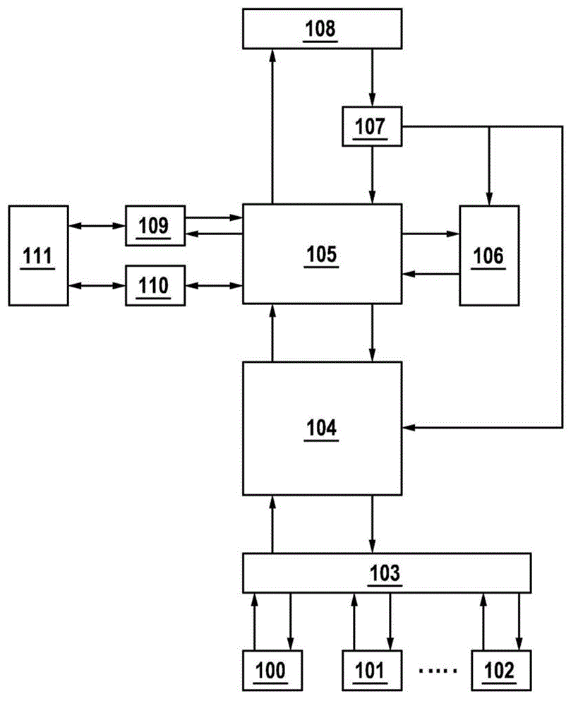
[0022] figure 1 A block diagram of an exemplary embodiment of the present invention is shown. Blocks 100 , 101 , 102 (hereinafter also referred to as sensor units) represent sensors such as accelerometer sensors, magnetic field sensors, gyroscopes, pressure sensors and / or proximity sensors. Block 103 serves as an abstraction layer between the sensor and data processing block 104 (hereinafter also referred to as first and second storage unit). The data processing block 104 includes, for each sensor, a data buffer, a sensor calibration device and a data correction device. The data buffer stores the most recently queried raw data for each sensor. Each sensor preferably uses two or more data buffers, wherein for example acceleration data with a bandwidth of 1000 Hz, low-pass filter data up to 200 Hz and up...


PUM


Abstract

The invention relates to a method for controlling an electric apparatus having a sensor unit, said apparatus being operated in a first potential motion mode and / or in a second potential motion mode and a sensor signal being generated in the sensor unit. Depending on a request for making a first information regarding the presence of the first potential motion mode and / or a second information regarding the presence of the second potential motion mode available, the first information and / or the second information is calculated as a function of the sensor signal.

Description

technical field [0001] The invention proceeds from a method according to the preamble of claim 1 and a device according to the preamble of claim 8 . Background technique [0002] To control devices, sensors are standard components in mobile phones, safety and health applications. Combinations of various sensors controlled by "smart software", so-called sensor clusters, penetrate the market, where eg mobile phones are equipped with acceleration sensors, magnetic sensors and gyroscopes together with "smart software". Customer experience and customer value are determined by application software and / or so-called "use cases" which use the data produced by the combined sensors and the results calculated by the software. The software can thus be implemented in the microprocessor running the sensor or in the system CPU (eg Linux libraries in an Android mobile phone) or exist as a key component of a user-installed application. Applications such as portrait / landscape image orientati...

Claims


Application Information

Patent Timeline
Patent Type & Authority Applications(China)
IPC IPC(8): G08B21/02
CPCH04Q2209/40G05B19/042H04W52/02G05B15/02H04W52/0245H04Q9/00H04W52/0264G05B2219/21065H04Q2209/84G08B21/02G06F3/0346G01P15/00H04W88/02H04W28/04Y02D30/70G06F9/06
Inventor D·席费德克尔F·本尼尼J·巴托洛麦奇克S·沙伊尔曼
Owner ROBERT BOSCH GMBH
Learn More