Hydraulic driving system of underwater acoustical generator

A driving system and sound generator technology, applied in the direction of the transducer used underwater, can solve the problems of increasing the length and complexity of the system pipeline, the single movement form of the hydraulic drive system, the size and weight of the sound generator, etc. Compact structure, low requirements on cleanliness and weight reduction

Inactive Publication Date: 2015-03-18
710TH RES INST OF CHINA SHIPBUILDING IND CORP
View PDF1 Cites 0 Cited by
  • Summary
  • Abstract
  • Description
  • Claims
  • Application Information

AI Technical Summary

Problems solved by technology

Compared with the electric system, the hydraulic system responds slowly and cannot adapt to the requirements of high-frequency drive
Moreover, the high-frequency sound field response of the rigid piston radiator has strong directivity, which cannot meet the requirements of minesweeping operations.
[0006] (2) Geometric size and weight are relatively large
[0007] The oil tank, oil pump and other components of the existing hydraulic sounder drive system are arranged independently, and there are many pipelines and complicated wiring, which makes the size and weight of the sounder relatively large, and the scope of application is limited.
[0008] (3) The system is complex and inconvenient to use
[0009] The existing hydraulic drive system adopts the servo control method, which has very high requirements on the filtration accuracy of hydraulic oil, resulting in complicated application preparation work, often requiring multiple filtration processes to ensure the accuracy of hydraulic oil
In addition, the existing hydraulic drive system requires more auxiliary units to complete the main functions, such as an independent cooling device, which increases the length and complexity of the system pipeline and reduces the system efficiency
[0010] (4) Single motion output form
[0011] The existing hydraulic drive system only has a single motion output

Method used


Image

  • Hydraulic driving system of underwater acoustical generator
  • Hydraulic driving system of underwater acoustical generator
  • Hydraulic driving system of underwater acoustical generator

Examples


Embodiment Construction

[0037] The present invention will be described in detail below with reference to the drawings and embodiments.

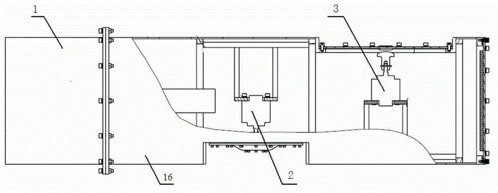
[0038] The new driving system of the sound generator for minesweeping provided by this embodiment controls two oil cylinders through a high-pressure oil source. The principle of the hydraulic driving system is as follows figure 1 As shown, high-pressure hydraulic oil is used as a power source, two independent oil cylinders are controlled as vibration output, and the sound radiating elements of two sound generators are respectively driven. In this embodiment, the sound radiating element of sound generator A is a rigid piston, and the sound radiating element of sound generator B is a diaphragm. Through the separate control of the two vibrating oil cylinders, two output types can be provided. The rigid piston is driven by the vibrating oil cylinder A to obtain the low-frequency radiation sound field, and the vibration oil cylinder B strikes the diaphragm to obtain the high...


PUM


Abstract

The invention discloses a hydraulic driving system of an acoustical generator underwater. The system utilizes high pressure hydraulic oil as a motive power source and controls more than two independent oil cylinders to be served as vibration output, each oil cylinder corresponds to an acoustic radiation element of the acoustical generator, so that a great deal of output is achieved. Meanwhile, each oil cylinder is controlled by two high-speed magnetic valves, so that connection control of flow quality is achieved, and due to the fact that the high-speed magnetic valves are high in response speed, the problems that a traditional hydraulic system is low in the response speed and cannot adapt to high-frequency driving are solved. The high-speed magnetic valves are high in response speed, high in reliability, simple in structure, small in size, low in failure rate and not high in requirements on clean degree of the hydraulic oil, besides, pressure drop on the valves is large, and interference problem cannot occur under a double-driving model. The hydraulic driving system of the acoustical generator underwater is capable of knocking a membrane board to radiate high-frequency sound fields, and therefore a range of a radiated sound field of the hydrostatic drive acoustical generator is expanded to high frequency.

Description

Technical field [0001] The invention relates to a hydraulic drive system, in particular to a hydraulic drive system of an underwater sounder. Background technique [0002] In acoustic minesweeping operations, the underwater sound generator is the most basic unit, and its types are mainly mechanical vibration type, hydraulic drive type, electric type, piezoelectric or magnetostrictive type, etc. The hydraulically driven sound generator has a large hydraulic power / weight ratio, can generate a strong low-frequency (including infrasound) sound field, has a strong low-frequency sound ability, and the low-frequency sound source level can exceed 190dB, and can be achieved underwater by controlling the hydraulic oil The sound field frequency spectrum control has obtained the advantages of low frequency and high sound level radiation sound field in a certain frequency range, and has been widely used. [0003] The existing hydraulic sounder mainly has the following disadvantages: [0004] (1...

Claims


Application Information

Patent Timeline
Patent Type & Authority Patents(China)
IPC IPC(8): H04R1/44
Inventor 李志远麻昔宋昭海寿丽莉艾艳辉官红柳占新束理
Owner 710TH RES INST OF CHINA SHIPBUILDING IND CORP
Why Eureka
Try Eureka